
The Structure of the Titanic: Engineering Marvel & Fatal Design Flaws
📌 Explore the Titanic’s intricate structure, including watertight compartments, electrical systems, lifeboats, and wireless technology. Discover how its engineering triumphs and shortcomings contributed to history’s most infamous maritime disaster. Essential for students, teachers, genealogists, and historians.

Titanic Outboard Profile, Boat Deck, and Orlop Deck Plans. International Marine Engineering (May 1912) p. 199. GGA Image ID # 1050d41670. Click to View a Larger Image.
The Structure of the Titanic – Engineering Triumph or Fatal Design? 🚢⚙️
The article "Structure of the Titanic" provides an in-depth technical analysis of the ship’s design, including its steel framework, watertight compartments, electrical installations, pumping systems, and life-saving appliances. This detailed blueprint of Titanic’s construction allows historians, students, genealogists, and maritime enthusiasts to understand both the ship’s engineering marvels and the flaws that led to its sinking.
📌 This article is a goldmine for educators and researchers who wish to explore the balance between innovation and oversight in shipbuilding, offering lessons in maritime safety, emergency preparedness, and technological advancement.
This article discusses the structure, water-tight subdivision, water-tight doors, side doors, accommodation ladder, masts and rigging, life-saving appliances, pumping arrangements, electrical installation, electric heating and power and mechanical ventilation, wireless telegraphy, and more.
Structure
The vessel was built of steel throughout and had a cellular double bottom of the usual type, with a floor at every frame. Its depth at the center line was 63 inches, except in the way of the reciprocating machinery, where it was 78 inches.
For approximately half the vessel's length, the double bottom extended up the ship's side to a height of 7 feet above the keel, a design that ensures maximum safety and stability.
Forward and aft of the machinery space, the inner bottom's protective reach extended to a lesser height above the keel. This meticulous design resulted in four separate water-tight compartments, a feature that enhances the vessel's safety and resilience.
Before and after the machinery space, there was a water-tight division at the center line only, except in the foremost and aftermost tanks. Above the double bottom, the vessel was constructed of the usual transverse frame system, reinforced by web frames that extended to the highest decks.
At the forward end, the framing and plating were strengthened to prevent panting and damage when meeting thin harbor ice.
Beams were fitted on every frame at all decks from the boat deck downward. An external bilge keel about 300 feet long and 25 inches deep was fitted along the bilge amidships.
The heavy ship's plating was carried right up to the boat deck, and the double plating between the C and B decks was also doubled. The stringer or edge plate of the B deck was also doubled. This double plating was hydraulic riveted.
All decks were steel-plated throughout.
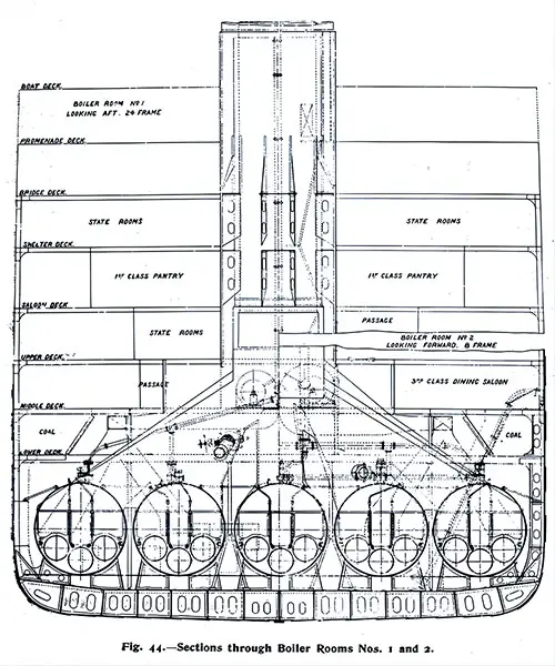
Fig. 44: Sections Through Boiler Rooms Nos. 1 and 2. The Shipbuilder (Midsummer 1911) p. 45. GGA Image ID # 10bcc0b520
The ship's transverse strength was in part dependent on the 15 transverse water-tight bulkheads, which were specially stiffened and strengthened to withstand the necessary pressure in the event of an accident. Double angles connected them to the decks, inner bottom, and shell plating.
The two decks above the B deck were of comparatively light scantling but strong enough to ensure they were proving satisfactory in these positions in rough weather.
Water-Tight Subdivision

Electrically Operated Bulkhead of the General Type Installed on the Titanic. Scientific American (27 April 1912) p. 380c. GGA Image ID # 10a419ff45
In preparing the design of this vessel, it was arranged that the bulkheads and divisions should be placed so that the ship would remain afloat in the event of any two adjoining compartments being flooded and that they should be built and strengthened so that the ship would remain afloat under this condition.
The minimum freeboard that the vessel would have in the event of any two compartments being flooded was between 2 feet 6 inches and 3 feet from the deck adjoining the top of the watertight bulkheads.
With this object in view, 15 watertight bulkheads were arranged in the vessel. The lower part of the C bulkhead was doubled, and a cofferdam formed.
The bulkheads were carried up in one plane to their upper sides as far as possible. Still, in cases where they had to be stepped forward or aft for any reason, the deck, in the way of the step, was made into a watertight flat, thus completing the compartment's watertightness.
In addition, the G deck in the after peak was made watertight. The orlop deck between bulkheads, which formed the top of the tunnel, was also watertight.
The orlop deck in the forepeak tank was also a watertight flat. A structure some distance from the ship's side further protected the electric machinery compartment, forming six separate watertight compartments to store fresh water.
Where openings were required for the ship's work in these watertight bulkheads, they were closed by watertight sliding doors that could be operated from a position above the top of the watertight bulkhead. Those doors immediately above the inner bottom had a special automatic closing pattern, as described below. By this subdivision, there were 73 compartments in all, 29 of which were above the inner bottom.
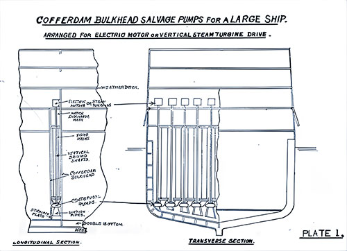
Plate 1: Cofferdam Bulkhead Salvage Pumps for a Large Ship. Arranged for Electric Motor or Vertical Steam Turbine Drive. Longitudinal Secion on Left; Transverse Section shown on Right. How to Save a Big Ship from Sinking (1915) p. 24. GGA Image ID # 10e998eb91
Water-Tight Doors
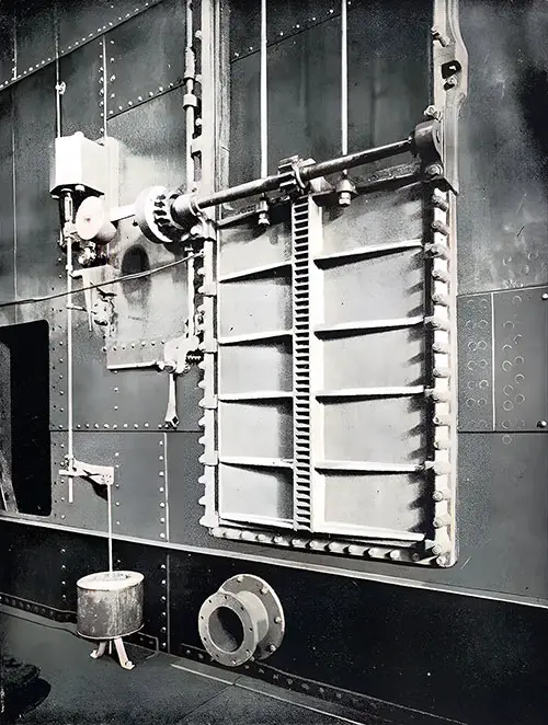
Fig. 21: Double Cylinder Watertight Door. The Shipbuilder (Midsummer 1911) p. 26. GGA Image ID # 10b623f05f
The doors (12 in number) immediately above the inner bottom were in the engine and boiler room spaces. They were of Messrs. Harland & Wolff's latest type, working vertically.
The doorplate was cast iron, had a heavy section, and was strongly ribbed. It closed by gravity and was held in the open position by a clutch, which could be released by means of a powerful electromagnet controlled from the captain's bridge.
In the event of an accident or at any time when it might be considered desirable, the captain or officer on duty could immediately close all these doors by simply moving an electric switch.
The time required for the doors to close was between 25 and 30 seconds. Each door could also be closed from below by operating a hand lever fitted alongside the door.
As a further precaution, floats were provided beneath the floor level, which, in the event of water accidentally entering any of the compartments, automatically lifted and thus released the clutches, thereby permitting the doors in that particular compartment to close if they had not already been dropped by any other means.
These doors were fitted with cataracts, which controlled the speed of closing. A warning bell gave due notice of closing from the bridge.
A ladder or escape was provided in each boiler room, engine room, and similar watertight compartment so that the men working therein could not be imprisoned by the doors closing at any time.
The watertight doors on E deck were of horizontal pattern, with wrought-steel doorplates. Those on F deck and the one aft on the Orlop deck were of similar type, but had cast-iron doorplates of heavy section, strongly ribbed.
Each of the between-deck and vertical doors on the tank top level could be operated by ordinary hand gear from the deck above the top of the watertight bulkhead and from a position on the next deck above, almost directly above the door.
Plates were affixed in suitable positions on the sides of the alleyways to facilitate the quick closing of the doors. To indicate the positions of the deck plates, a box spanner was provided for each door, hanging in suitable clips alongside the deck plate.
Ship's Side Doors
Large side doors were provided through the side plating, giving access to passengers' or crew's accommodation as follows:
There is one baggage door on the saloon (D) deck on the starboard side in the forward third-class open space.
Two doors close together on each side toward the first-class entrance forward.
On the upper (E) deck, one door on each side at the forward end of the working passage.
One door leading into the working passage is on the port side, opposite the engine room. One door on each side of the port and starboard sides aft into the forward second-class entrance.
All the doors on the upper deck were secured by lever handles and made watertight using rubber strips. Those on the saloon deck were closed by lever handles but had no rubber.
Accommodation Ladder
One teak accommodation ladder was provided and could be worked on either side of the ship in the gangway door opposite the second-class entrance on the upper deck (E).
It had a folding platform, portable stanchions, hand rope, etc. The ladder extended to within 3 feet 6 inches of the vessel's light draft and was stowed overhead in the entrance adjacent to the forward second-class main staircase. Its lower end was arranged so that it could be raised and lowered from a davit immediately above.
Masts and Rigging
The vessel was rigged with two masts and fore and aft sails. The two pole masts were constructed of steel and stiffened with angle irons. The poles at the top of the mast were made of teak.
A steel lookout cage was fitted on the foremast at about 95 feet above the water line. Access to the cage was obtained by an iron vertical ladder inside the foremast, with an opening at the C deck and one at the lookout cage. An iron ladder was fitted on the foremast from the hounds to the masthead light.
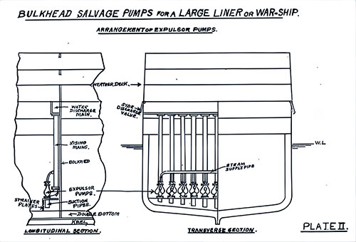
Plate 2: Bulkhead Salvage Pumps for a Large Liner or War Ship. Arrangement of Expulsor Pumps. Longitudinal Secion on Left; Transverse Section shown on Right. How to Save a Big Ship from Sinking (1915) p. 25. GGA Image ID # 10e9d45a81
Life-Saving Appliances
Lifebuoys —Forty-eight, with beckets, were supplied with a pattern approved by the board of trade. They were placed about the ship.
Life belts —Three thousand five hundred and sixty life belts of the latest improved overhead pattern, approved by the board of trade, were supplied and placed on the ship. The board of trade inspected them. These were distributed throughout all the sleeping accommodations.
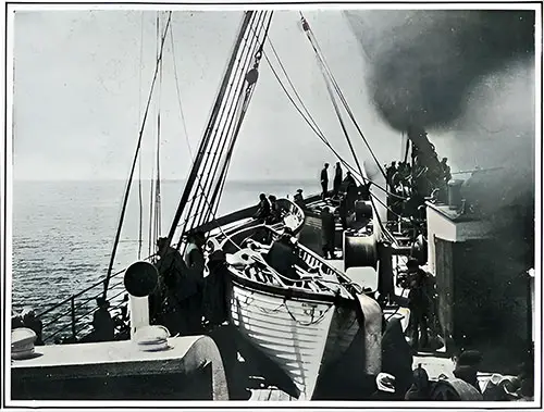
Some of the Titanic’s Lifeboats on the Deck of the Carpathia. Harper's Weekly (27 April 1912) p. 36a. GGA Image ID # 109dd0500d
Lifeboats —Twenty boats in all were fitted on the vessel and were of the following dimensions and capacities:
Fourteen wood lifeboats, each 30 feet long by 9 feet 1 inch broad by 4 feet deep and with a cubic capacity of 655.2 cubic feet, were constructed to carry 65 persons each.
Emergency boats:
One wood single-masted rig cutter boat, 25 feet 2 inches long by 7 feet 2 inches broad by 3 feet deep, with a cubic capacity of 326.6 cubic feet, constructed to carry 40 persons.
One wood single-masted rig cutter, 25 feet, 2 inches long by 7 feet 1 inch broad by 3 feet deep, with a cubic capacity of 322.1 cubic feet, constructed to carry 40 persons.
Four Engelhardt collapsible boats, 27 feet 5 inches long by 8 feet broad by 3 feet deep, with a cubic capacity of 376.6 cubic feet, constructed to carry 47 persons each.
Or a total of 11,327.9 cubic feet for 1,178 persons.
The lifeboats and cutters were constructed as follows: the keels were of elm, the stems, and stern posts were of oak, and they were all clinker-built of yellow pine, double fastened with copper nails, and clinched over rooves.
The timbers were elm, spaced about 9 inches apart, and the seats were pitch pine, secured with galvanized-iron double knees. The buoyancy tanks in the lifeboats were 18-ounce copper and of capacity to meet the board of trade requirements.
The lifeboats were fitted with Murray's disengaging gear, with arrangements to free both ends if required. The gear was fastened at a suitable distance from the forward and after ends of the boats to suit the davits. Life fines were fitted around the gunwales of the lifeboats. The davit blocks were treble for the lifeboats and double for the cutters.
They were of elm, with lignum vitae roller sheaves, were bound inside with iron, and had swivel eyes. There were manila rope falls of sufficient length for lowering the boats to the vessel's light draft, and when the boats were lowered to reach the ship, winches were on the boat deck.
The lifeboats were stowed on hinged wood chocks on the boat deck in groups of three at the forward and four at the afterends. On each side of the boat deck, the cutters were arranged forward of the group of three and fitted to lash outboard as emergency boats.
They were immediately abaft the navigating bridge. The Engelhardt collapsible lifeboats were stowed abreast of the cutters, one on each side of the ship, and the remaining two on top of the officers' house, immediately abaft the navigating bridge.
The boat equipment was in accordance with the board of trade requirements. Sails for each lifeboat and cutter were supplied and stowed in painted bags.
Covers were supplied for the lifeboats and cutters, and a sea anchor for each boat. Every lifeboat was furnished with a special spirit boat compass and fitting for holding it; these compasses were carried in a locker on the boat deck. A provision tank and water beaker were supplied to each boat.
Compasses -— Compasses were supplied as follows:
One Kelvin standard compass has an azimuth mirror on the compass platform.
One Kelvin steering compass inside of wheelhouse.
One Kelvin steering compass on the captain's bridge.
One light card compass for docking bridge.
Fourteen spirit compasses for lifeboats.
All the ships' compasses were lighted with oil and electric lamps. Messrs. C. J. Smith, of Southampton, adjusted them on the passage from Belfast to Southampton and Southampton to Queenstown.
Charts — All the necessary charts were supplied
Distress Signals—These were supplied in the number and pattern approved by the Board of Trade—i.e., 36 socket signals in lieu of guns, 12 ordinary rockets, 2 Manwell Holmes deck flares, 12 blue lights, and 6 lifebuoy lights.
Pumping Arrangements

The Midship Section of the Titanic Showing Single Skin above the Double Bottom and the Absence of Longitudinal Bulkheads. Popular Mechanics Magazine (June 1912) p. 804-a. GGA Image ID # 10819412ed
The general piping arrangement was designed so that two independent systems of 10-inch mains with cross-connections between them could pump from any flooded compartment.
Rods controlled these from above, and wheels led to the level of the bulkhead deck. These made it possible to isolate any flooded space, and any suctions in it.
If any of these should happen accidentally to be left open and consequently out of reach, it could be shut off from the main by the wheel on the bulkhead deck. This arrangement was specially submitted to the Board of Trade and approved by them.
The double bottom of the vessel was divided by 17 transverse watertight divisions, including those bounding the fore and aft peaks, and again subdivided by a center fore-and-aft bulkhead and two longitudinal bulkheads into 46 compartments.
Fourteen of these compartments had 8-inch suctions, 23 had 6-inch suctions, and 3 had 5-inch suctions connected to the 10-inch ballast main suction; 6 compartments were used exclusively for fresh water.
The following bilge suctions were provided for dealing with water above the double bottom: No. 1 holds two 3 ½ inch suctions, No. 2 holds two 3 ½ inch and two 3-inch suctions, and the bunker holds two 3 ½ inch and two 3-inch suctions.
The valves connected to the forward bilge and ballast suctions were placed in the firemen's passage, the watertight pipe tunnel extending from the No. 6 boiler room to the after end of the No. 1 hold.
In this tunnel, in addition to two 3-inch bilge suctions, one at each end, a special 3-inch suction with valve rod led up to the lower deck above the load line, so it was always accessible should the tunnel be flooded accidentally.
- There were three 3 ½ inch, one 4 ½ inch, and two 3-inch suction in the No. 6 boiler room.
- There were three 3 ½ inch, one 5-inch, and two 3-inch suctions in the No. 5 boiler room.
- There were three 3 ½ inch, one 4 ½ inch, and two 3-inch suction in the No. 4 boiler room.
- The No. 3 boiler room had three 3 ½ inch, one 5-inch, and two 3-inch suction.
- The No. 2 boiler room had three 3 ½ inch, one 5-inch, and two 3-inch suctions.
- There were two 3 ½ inch, one 5-inch, and two 3-inch suctions in the No. 1 boiler room.
- There were two 3 ½ inch, six 3-inch, two 18-inch, and two 5-inch suctions in the reciprocating engine room.
- The turbine engine room had two 3 ½ inch, three 3-inch, two 18-inch, two 5-inch, and one 4-inch suctions.
- In the electric engine room, there were four 3 ½ inch suctions.
- In the storerooms above the electric engine room, there was one 3-inch suction.
- In the forward tunnel compartment, there were two 3 ½ inch suctions.
- In the watertight flat over the tunnel compartment, there were two 3-inch suctions.
- In the tunnel after compartment, there were two 3 ½ inch suctions.
- In the watertight flat over the tunnel after compartment, there were two 3-inch suctions.
from "How to save a big ship from sinking – p 92
The main drive is centrifugal bulkhead salvage pumps for large ships, with bulkheads forming one side of pumps and pipes.
Electrical Installation
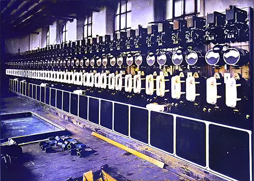
Fig. 126: Main Feeder Switchboard. The Shipbuilder (Midsummer 1911) p. 112. GGA Image ID # 10dd72f3e9
Main Generating Sets
There were four engines and dynamos, each with a capacity of 400 kilowatts at 100 volts, and a vertical three-crank compound-forced lubrication enclosed engine of sufficient power to drive the electrical plant. The engines were direct-coupled to their respective dynamos.
These four main sets were situated in a separate watertight compartment about 63 feet long by 24 feet high, adjoining the end of the turbine room at the level of the inner bottom.
Steam to the electric engines was supplied from two separate lengths of steam pipes, connecting on the port side to the five single-ended boilers in compartment No. 1 and two in compartment No. 2, and on the starboard side to the auxiliary steam pipe, which derived steam from the five single-ended boilers in No. 1 compartment, two in No. 2, and two in No. 4. By connections at the engine room forward bulkhead steam could be taken from any boiler in the ship.
Auxiliary Generating Sets
In addition to the four main generating sets, there were two 30-kilowatt engines and dynamos on a platform in the turbine engine room casing on saloon deck level, 20 feet above the water line. They were the same general type as the main sets.
These auxiliary emergency sets were connected to the boilers by means of a separate steam pipe running along the working passage above the E deck, with branches from three boiler rooms, Nos. 2, 3, and 5. This way, should the main sets be temporarily out of action, the auxiliary sets could provide current for such lights and power appliances as would be required in an emergency.
Electric Lighting
The total number of incandescent lights was 10,000, ranging from 16 to 100 candlepower. The majority were of the Tantalum type, except in the cargo spaces and for the portable fittings, where carbon lamps were provided. Special dimming lamps with a small amount of light were provided in the first-class rooms.
Electric heating and power and mechanical ventilation

Fig. 128: Electric Heater. The Shipbuilder (Midsummer 1911) p. 113. GGA Image ID # 10de3c34fc
Overall, 562 electric heaters and 153 electric motors were installed throughout the vessel, including six 50-hundred-pound and two 30-pound cranes, four 3-ton cargo winches, and four 15-pound boat winches.
There were also four electric passenger lifts, three forward of the first-class main entrance and one in the second-class forward entrance, each capable of carrying 12 persons.
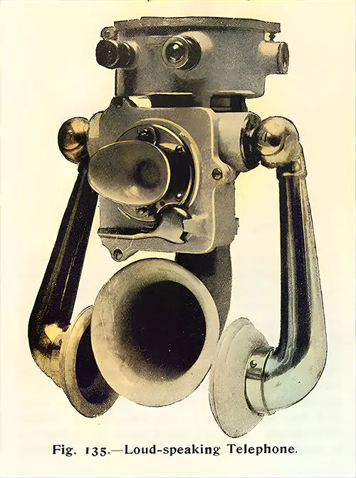
Fig. 135: Loud-Speaking Telephone. The Shipbuilder (Midsummer 1911) p. 117. GGA Image ID # 10df4cc8bd
Telephones
Loud-speaking telephones of the navy pattern were fitted for communication between the following:
- Wheelhouse on the navigating bridge and the forecastle.
- Wheelhouse is on the navigating bridge, and the lookout station is on the crow's nest.
- Wheelhouse is on the navigating bridge and in the engine room.
- Wheelhouse on the navigating bridge and the poop.
- Chief engineer's cabin and the engine room.
- Engine room and Nos. 1, 2, 3, 4, 5, and 6 stokeholds.
These were operated from the ship's lighting circuit through a motor generator and, alternatively, by a stand-by battery, which, utilizing an automatic switch, could be introduced into the circuit should the main supply fail.
There was also a separate telephone system for intercommunication between a number of the chief officials and service rooms through a 50-line exchange switchboard.
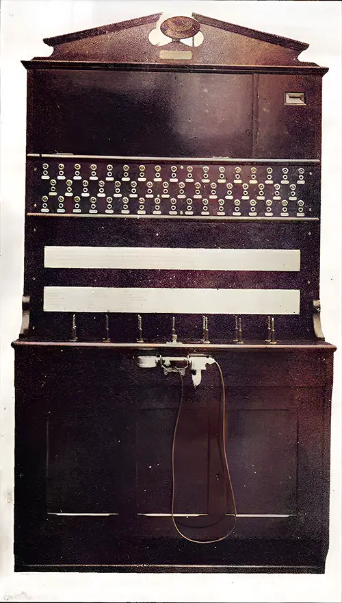
Fig. 136: Telephone Exchange Switchboard. The Shipbuilder (Midsummer 1911) p. 118. GGA Image ID # 10df529f1e
A number of the pantries and galleys were also in direct telephonic communication.
The wireless telegraphy system was operated by a Marconi 5-kilowatt motor generator. The house for the Marconi instruments was situated on the boat deck close to the bridge.
Four parallel aerial wires extended between the masts, fastened to light booms; from the aerials, the connecting wires led to the instruments in the house.
There were two complete sets of apparatus, one for transmitting and one for receiving messages. The former was placed in a sound-proof chamber in one corner of the wireless house.
In the event of the failure of the current supply, which came from the ship's dynamos, there was also an independent storage battery and coil.
Submarine Signaling
The Submarine Signal Co.'s apparatus was provided to receive signals from the submarine bells. Small tanks containing the microphones were placed on the inside of the vessel's hull on the port and starboard sides below the water level. They were connected by wires to receivers situated in the navigating room on the port side of the officer's deck house.
Various
The Willett Bruce system's whistles were electrically actuated. The boiler-room telegraphs, stoking indicators, rudder indicators, clocks, and thermostats were also electrical. Electric magnets released the watertight doors.
Emergency Circuit
A separate and distinct installation was fitted in all parts of the vessel, deriving current from the two 30-kilowatt sets mentioned above. This ensured that in the event of the current from the main dynamos being unavailable, an independent supply was obtainable.
Over 500 incandescent lamps fitted throughout all passenger, crew, and machinery compartments, at the end of passages, near stairways, and on the boat deck were connected to the emergency circuit, enabling anyone to find their way from one part of the ship to another.
The following were also connected to the emergency circuit by means of change-over switches: five lamps, seven cargo and gangway lanterns, Marconi apparatus, mast, side, and stern lights, all lights on the bridge, including those for the captain's, navigating, and chat rooms, wheelhouse, telegraphs, and Morse signaling lanterns, and four electrically driven boat winches.
These latter, situated on the boat deck, were each capable of lifting a load of 15 hundredweight at a speed of 100 feet per minute.
Ventilating
There were 12 electrically-driven fans for supplying air to the stokeholds and six electrically-driven fans for engine and turbine room ventilation. There were fans for the engine and boiler rooms.
Bibliography
Congressional Serial Set 1912 – Loss of the steamship “Titanic,” Loss of the steamship Titanic - Presented by Mr. Smith of Michigan - August 20, 1912 - p. 571
⚙️ Titanic’s Structure: Engineering Masterpiece or Overconfidence?
📜 Most Engaging Image:
🔹 "Titanic Outboard Profile, Boat Deck, and Orlop Deck Plans" – A highly detailed technical drawing of Titanic’s exterior and decks.
💡 Why It Matters:
This image offers a comprehensive view of Titanic’s structural integrity, helping researchers understand its layout and how flooding impacted its compartments.
🔩 Key Engineering Facts About Titanic’s Construction
✅ Constructed entirely of steel with a cellular double bottom for strength
✅ 15 watertight bulkheads designed to keep the ship afloat if two compartments flooded
✅ Steel plating reinforced to handle icy waters
✅ 300-foot-long external bilge keel to stabilize the ship
✅ Hydraulic riveted plating for additional strength
💡 The Fatal Flaw:
🔹 Titanic’s watertight bulkheads did not extend high enough. Water spilled over them like a cascading waterfall, dooming the ship.
🔹 The outer hull was single-plated instead of double-plated, making it more vulnerable to punctures.
🚢 Watertight Compartments: An Illusion of Safety?
📜 Most Engaging Image:
🔹 "Electrically Operated Bulkhead on Titanic" – A visual of the Titanic’s watertight doors, which were supposed to keep the ship afloat.
💡 Why It Matters:
This image shows how the bulkhead system was designed to prevent flooding but ultimately failed.
🔹 Titanic’s Water-Tight Subdivision
✅ 73 compartments in total (29 above the inner bottom)
✅ 15 transverse watertight bulkheads to prevent flooding
✅ Watertight doors could be controlled from the bridge and closed in 25-30 seconds
✅ Automatic float triggers closed doors if water entered
💡 What Went Wrong?
🔹 The bulkheads only reached E Deck, meaning once water topped them, it spread uncontrollably.
🔹 The collision with the iceberg compromised multiple compartments, exceeding the ship’s safety limits.
🔹 No longitudinal bulkheads (running lengthwise) meant that water could spread sideways, increasing the flooding rate.
🚨 Lesson Learned: Olympic (Titanic’s sister ship) was later upgraded with higher bulkheads, which might have saved Titanic.
🛳️ Lifeboats & Safety Equipment: A Deadly Shortage
📜 Most Engaging Image:
🔹 "Some of the Titanic’s Lifeboats on the Deck of the Carpathia" – A chilling reminder that there were too few lifeboats, and many left half-empty.
💡 Why It Matters:
This image highlights the failures in Titanic’s emergency preparedness and evacuation procedures.
🚣 Titanic’s Lifeboat & Safety Equipment
✅ 48 lifebuoys and 3,560 life belts
✅ 20 lifeboats (14 wood, 2 cutters, 4 collapsible) – designed for only 1,178 people out of 2,200+ on board
✅ Davits (boat cranes) could hold 64 boats, but only 20 were installed
✅ Compasses, flares, and distress signals were provided but could not make up for lifeboat shortages
💡 What Went Wrong?
🔹 Lifeboats were launched half-full due to panic and poor evacuation planning.
🔹 The “unsinkable” myth led to overconfidence—lifeboats were considered unnecessary.
🔹 Collapsible lifeboats were difficult to use, causing further delays.
🚨 Lesson Learned: Lifeboats became mandatory for all passengers after Titanic’s sinking.
⚡ Titanic’s Electrical & Wireless Systems: A Technological Marvel
📜 Most Engaging Image:
🔹 "Main Feeder Switchboard" – A view of Titanic’s electrical control panel, showcasing its advanced power systems.
💡 Why It Matters:
This image highlights how Titanic was ahead of its time in electrical engineering, ensuring power distribution across the massive ship.
💡 Advanced Electrical Systems on Titanic
✅ 10,000 light bulbs (a rarity for ships of that era)
✅ 4 main generators producing 400 kW each
✅ Emergency generators placed above the waterline
✅ Electric heating, telephones, and ventilators throughout the ship
💡 Wireless Telegraphy: Titanic’s Last Hope
- Operated using a 5 kW Marconi transmitter
- Transmitted distress signals up to 400 miles
- Saved 700+ lives by contacting the Carpathia
- Lack of regulations allowed amateur signals to interfere with rescue efforts
🚨 Lesson Learned: After Titanic, wireless telegraphy became mandatory on passenger ships.
⚠️ Titanic’s Pumping System: Could It Have Saved Her?
📜 Most Engaging Image:
🔹 "Midship Section of Titanic, Showing Absence of Longitudinal Bulkheads" – Demonstrates why Titanic filled with water so rapidly.
💡 Why It Matters:
This image explains how Titanic’s design flaws contributed to its rapid sinking.
🛠️ Titanic’s Pumping & Flood Control System
✅ 46 compartments in the double bottom for extra buoyancy
✅ Independent pumping systems to remove water
✅ Valves controlled from above deck for emergency shutdown
💡 What Went Wrong?
🔹 The pumps couldn’t keep up with the flooding caused by the iceberg’s massive 300-foot gash.
🔹 Bulkheads didn’t prevent water from spilling over and overwhelming the ship.
🔹 The ship was designed to stay afloat with two flooded compartments, but six flooded instantly.
🚨 Lesson Learned: Future ships had stronger hulls, better bulkhead design, and more effective pumping systems.
📖 Who Should Study This?
👨🏫 Teachers & Students
- Perfect for STEM education on shipbuilding, physics, and safety engineering.
- An excellent case study on overconfidence in engineering.
📚 Historians & Maritime Enthusiasts
- Breaks down Titanic’s structural design and why it failed.
- Explains how Titanic’s disaster reshaped maritime laws.
🔎 Genealogists & Family Researchers
- Provides insights into where ancestors may have been aboard Titanic.
- Explains why survival chances depended on location within the ship.
🚢 The Titanic’s Engineering Legacy: A Lesson in Innovation & Hubris
The "Structure of the Titanic" is not just about blueprints—it’s about the human cost of engineering miscalculations. Titanic’s design pushed the limits of technology, but its flaws sealed its fate.
📜 Final Noteworthy Image:
🔹 "Cross-Section View of the Altered Olympic" – A powerful reminder of how Titanic’s tragedy forced safety improvements.
💡 Final Takeaway:
Titanic was a masterpiece—but an incomplete one.
Lessons from its sinking reshaped maritime laws forever.
⚓ What Do You Think?
🔹 Could Titanic have been saved with better bulkheads?
🔹 How did overconfidence in engineering lead to disaster?
🔹 What modern safety features exist because of Titanic?
💬 Share your thoughts by writing an essay using the materials on the GG Archives today! ⚓🚢📜