Building Titanic: The Engineering and Design of a Maritime Icon – Hull Construction, Riveting, and Launch
📌 Explore the construction of Titanic’s hull in this in-depth study from The Shipbuilder (1911). Learn about its steel framework, riveting techniques, watertight doors, and launching process. A must-read for maritime historians, educators, and genealogy researchers
The Shipbuilder – Building the Hulls ⚓🏗️
Introduction: The Strength Behind Titanic’s Legacy
This section of The Shipbuilder’s 1911 special issue focuses on the construction of Titanic and Olympic’s hulls, one of the most critical and complex aspects of shipbuilding. The hull—the skeletal and protective body of the ship—was engineered for strength, stability, and efficiency, making it one of the most advanced maritime structures of its time.
For historians, students, genealogists, and maritime enthusiasts, this article offers detailed technical insights, blueprints, and rare photographs documenting the birth of these legendary ships. With over three million rivets, a sophisticated stern design, and watertight doors that were considered state-of-the-art in 1911, Titanic’s construction represented a new era in ocean travel—though, tragically, one that would soon be tested in ways never anticipated.
Table of Contents in This Section
1️⃣ The Structural Design of Titanic and Olympic
2️⃣ Dimensions and Comparisons with Other Ships
3️⃣ Riveting and Steel Framework
4️⃣ Titanic’s Stern and Propeller Design
5️⃣ Watertight Doors and Safety Measures
6️⃣ The Construction Process: Photographic Timeline
7️⃣ The Launch of Olympic and Titanic
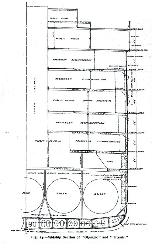
The structural design of the Olympic and Titanic is shown by the midship section (Fig. 14) and the elevation on Plate III. There are eight steel decks amidships—the boat deck, promenade deck (A), bridge deck (B), shelter deck (C), saloon deck (D), upper deck (E), middle deck (F), and lower deck (G)—while at the ends an extra deck—known as the orlop deck—is fitted, making nine decks in all.
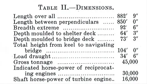
Table II: Dimensions of the Olympic and Titanic as Constructed. A comparison of the foregoing information with the table of dimensions of other vessels given in the preceding chapter will show that the Great Küstern was 170 feet shorter and 20,600 gross tons less; the Kaiser Wilhelm II and the Kronprinzessin Cecilie are each 172 feet shorter and 25,600 tons less; the Adriatic 141 feet shorter and 20,500 tons less; and the Mauretania 90 feet shorter and about 13,000 tons less. The Shipbuilder, Midsummer 1911. GGA Image ID # 10b4e3d3a4
Fig 14: Midship Section of the Olympic and Titanic. The Shipbuilder, Midsummer 1911. GGA Image ID # 10b502c25a. Click to View a Larger Image.
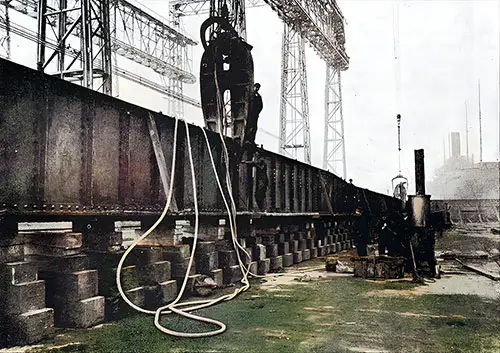
Fig. 15: Hydraulic Riveter at Work on the Vertical Keel Plate. The Shipbuilder, Midsummer 1911. GGA Image ID # 10b50e8f7c
Some idea of the great importance of the riveting in the SS Olympic and SS Titanic will be gathered from the fact that there are half a million rivets in the double bottom of each vessel, weighing about 270 tons, the largest rivets being 1¼ diameter; in each ship, when completed, there will be something like three million rivets weighing about 1,200 tons.
To ensure the best artistry, hydraulic riveting has been adopted whenever possible. The hydraulic power has riveted nearly all of the double bottom, including the bottom shell plating up to the turn of the bilge and the topside shell and stringer plates and doublings. A hydraulic riveter is at work on the vertical keel plate of the SS Olympic, as shown in Fig. 15, and the adjacent portable furnace is being used for heating the rivets.
Similar riveters can also be observed in several illustrations showing the various stages in the ship's building. The great extent and strong appearance of the topside hydraulic riveting are very clearly shown in Fig. 16. It is the responsibility of all of us, as engineers, shipbuilders, and maritime historians, to continue this tradition of excellence in ship construction.
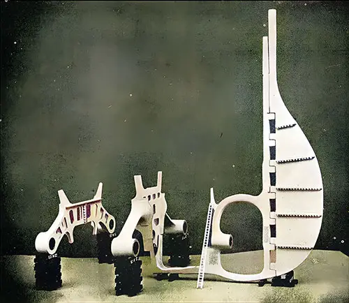
Fig. 17: Arrangement of Stern Castings. The Stern Frame, a Crucial Component in Ship Construction, Plays a Significant Role in Supporting a Ship’s Tail Shaft and Rudder. the Stern Frame Was Cast in Older Vessels and Then Welded to the Ship’s Outer Shell Plating. It Is the Usual Practice That the Stern Frame Is Made at a Location Away From the Shipyard. The Shipbuilder, Midsummer 1911. GGA Image ID # 10b57a1091
The general layout of the stern castings for the SS Olympic and SS Titanic is depicted in Figure 17. Each vessel is equipped with triple screws, with the stern frame featuring a boss and an aperture for the central turbine propeller.
In contrast, the wing or reciprocating propeller shafts are supported by boss arm castings, around which the shell plating is secured to create “bossing” of the improved type developed by Messrs. Harland and Wolff.
The Darlington Forge Company supplies all these castings. They are made from Siemens-Martin mild cast steel, except for the rudder stock, which is constructed from forged ingot steel.
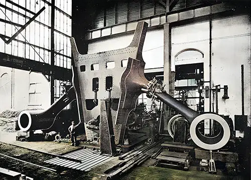
Fig. 18: After Propeller Brackets. The Giant Propellers Would Be Attached to This After Propeller Brackets Were Utilized as a Frame to Support Bearings for Shafts Outside of Regular Stern Framing. See Plate XV (N&K). The Shipbuilder, Midsummer 1911. GGA Image ID # 10b587dead
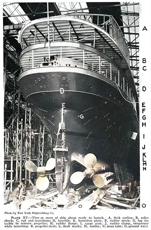
Plate XV—View at stern of ship about ready to launch. A. deck carlins; B. roller chock; C, rail and stanchions; D, knuckle; E. horseshoe plate; F. rudder stock; G, lug for tackle to remove propeller; H. rudder flange; I, cargo port; J. rudder clamp, temporary while launching; K. propeller strut; L, draft marks; M, rudder; N. stern tube; O, ground ways. Photo by New York Shipbuilding Company. Modern Shipbuilding Terms Defined and Illustrated, 1918. GGA Image ID # 2241349d8e
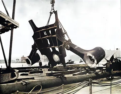
Fig 19: After Propeller Brackets Being Weighed. The Shipbuilder, Midsummer 1911. GGA Image ID # 10b5d58d5e
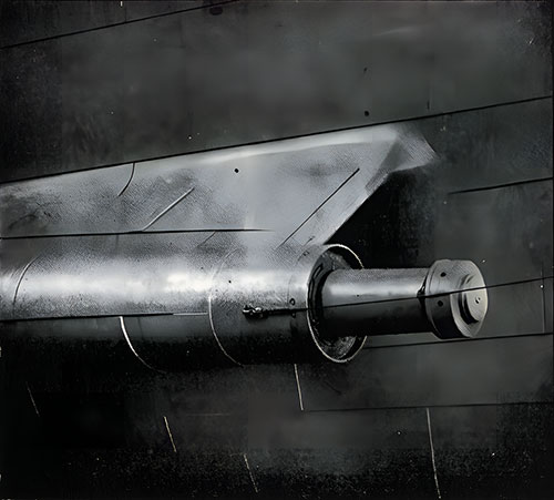
Fig 20. Shell Plating in Way of Bossing. © Frank & Sons, So. Shields. The Shipbuilder, Midsummer 1911. GGA Image ID # 10b5ddb1c3
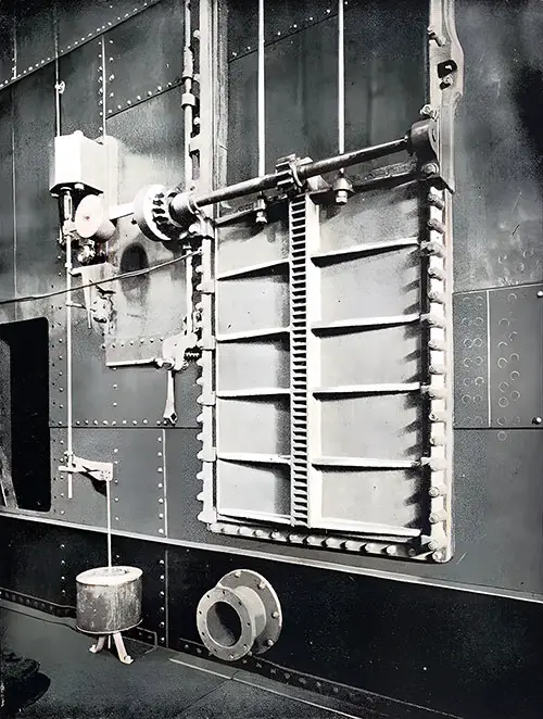
Fig. 21: Double Cylinder Watertight Door. The Shipbuilder, Midsummer 1911. GGA Image ID # 10b623f05f
The watertight doors, which serve as communication points between the various boiler rooms and engine rooms, are arranged on the drop system as usual in White Star vessels. They are of Messrs. Harland and Wolff's unique design of massive construction, as seen in Fig. 21.
These doors are protected with oil cataracts governing the closing speed, ensuring a swift and efficient closure. Each door is held in the open position by a suitable friction clutch, which can be instantly released utilizing a powerful electro-magnet controlled from the captain's bridge.
This system allows for an instant closure of the doors throughout the vessel, making it practically unsinkable in the event of an accident or when it may be considered advisable. A lever fitted with the friction clutch can also close each door below.
As a further precaution, floats are provided beneath the floor level, which, in the event of water accidentally entering any of the compartments, automatically lift and thereby close the doors opening into that compartment if those in charge of the vessel have not already dropped them.
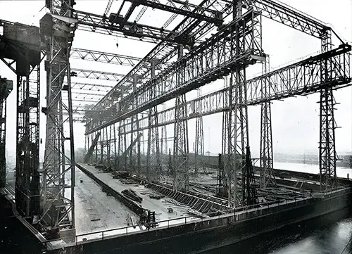
Fig. 22: The Olympic's Keel, Laid 1 January 1909. The Shipbuilder, Midsummer 1911. GGA Image ID # 10b63e4c62
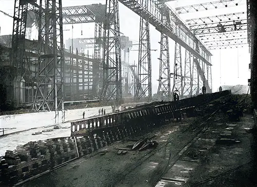
Fig. 23: Vertical Keel Plate and Floors, Looking Forward. Photograph dated 18 February 1909. The Shipbuilder, Midsummer 1911. GGA Image ID # 10b66005d8
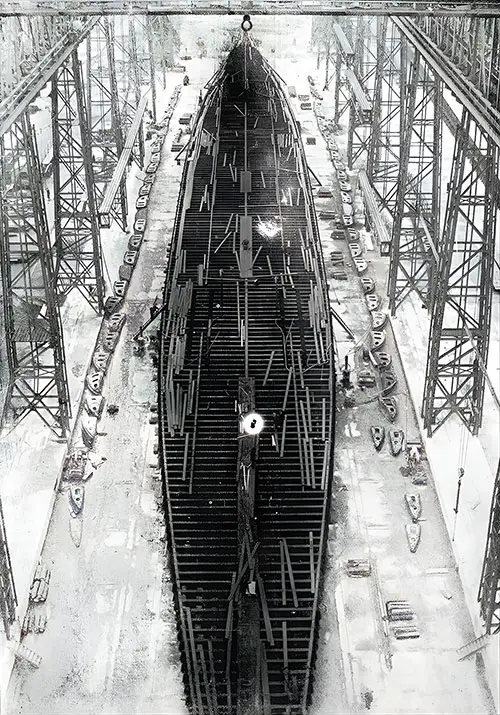
Fig. 24: Bird's Eye View of the Olympic from Top of Gantry. Photograph dated 15 April 1909. The Shipbuilder, Midsummer 1911. GGA Image ID # 10b6c36655
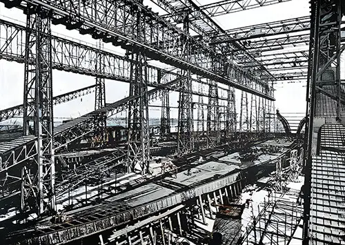
Fig. 25: Tank Top and After End Framing of the Olympic. Photograph dated 30 July 1909. The Shipbuilder, Midsummer 1911. GGA Image ID # 10b6cc6fda
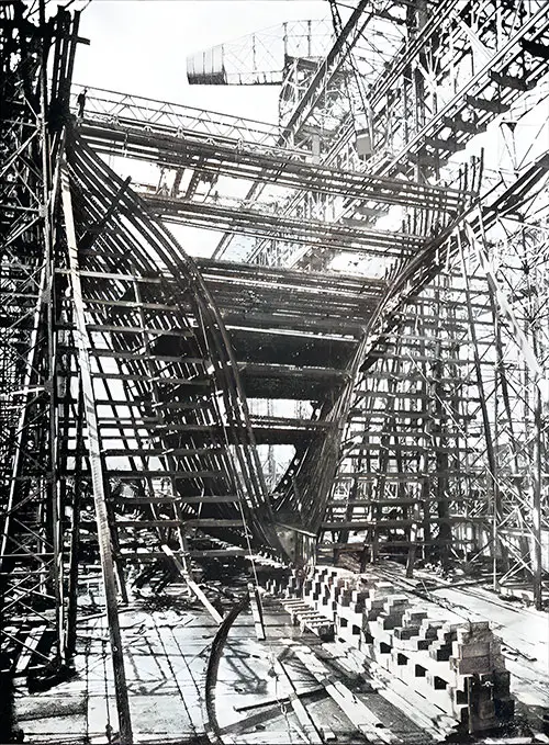
Fig. 26: After End Framing of the Olympic. Photograph dated 30 July 1909. The Shipbuilder, Midsummer 1911. GGA Image ID # 10b6d91a84

Fig. 27. The Olympic Almost Framed. Photograph dated 18 November 1909. The Shipbuilder, Midsummer 1911. GGA Image ID # 10b6eb31a6
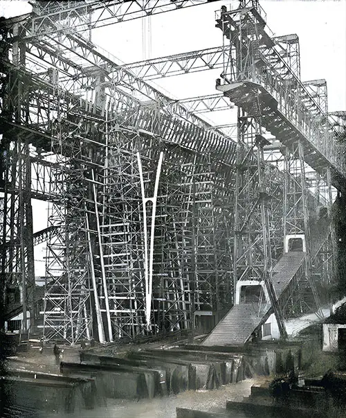
Fig. 28. Last Frame of the Olympic Being Raised. Photograph Dated 20 November 1909. The Shipbuilder, Midsummer 1911. GGA Image ID # 10b6f6618d

Fig. 29: View of the Olympic's Shelter Deck, Looking Aft. Photograph dated 31 March 1910. The Shipbuilder, Midsummer 1911. GGA Image ID # 10b70895fe
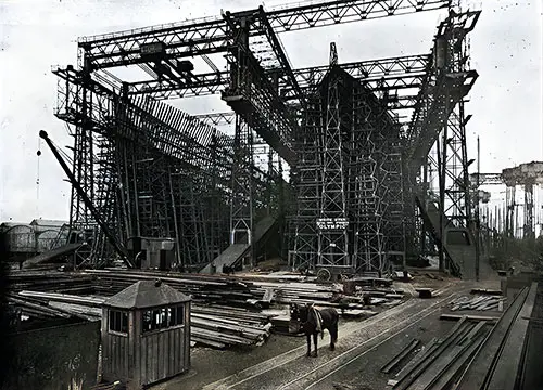
Fig 30: The Olympic Plated and the Titanic Framed. Photograph dated 7 April 1910. The Shipbuilder, Midsummer 1911. GGA Image ID # 10b755aa66
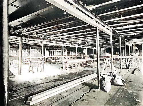
Fig. 31: Progress of Work in the Olympic's First Class Dining Saloon. Photograph dated 6 June 1910. The Shipbuilder, Midsummer 1911. GGA Image ID # 10b8164bda
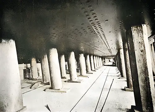
Fig. 32: Shoring Under the Olympic's Bottom. The Shipbuilder, Midsummer 1911. GGA Image ID # 10b8172c9a
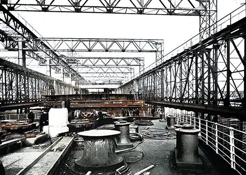
Fig. 33: Forecastle Deck of the Olympic, Looking Aft. The Shipbuilder, Midsummer 1911. GGA Image ID # 10b8a23210
![]()
Fig. 34: The Titanic and Olympic on the Stocks. Photographed on the Day the Olympic was Launched. © Frank & Sons, So. Shields. The Shipbuilder, Midsummer 1911. GGA Image ID # 10b9225e7a
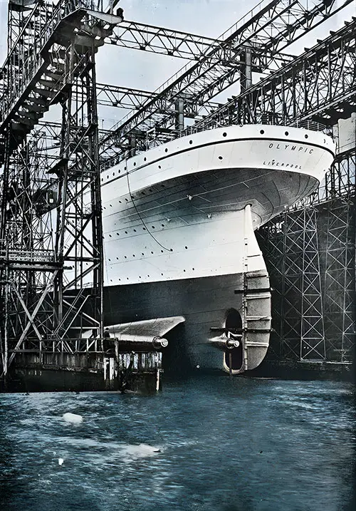
Fig. 35: The Stern of the Olympic Immediately Before Launching. © Frank & Sons. The Shipbuilder, Midsummer 1911. GGA Image ID # 10b963417c
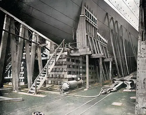
Fig. 36: Forward Launching Cradle. The Shipbuilder, Midsummer 1911. GGA Image ID # 10b9b88974
The SS Olympic was successfully launched on the 20th of October 1910, in the presence of the Lord Lieutenant of Ireland, the Countess of Aberdeen, and several distinguished guests, the final arrangements being personally directed by Lord Pirrie. The launching operation has already been fully dealt with in The Shipbuilder, and from our previous article, we reproduce Figs. 36 and 37 show the forward launching cradle and brackets.

Fig. 37: Forward Cradle and Make-Up of Ways. © Frank & Sons, So. Shields. The Shipbuilder, Midsummer 1911. GGA Image ID # 10ba8242d3
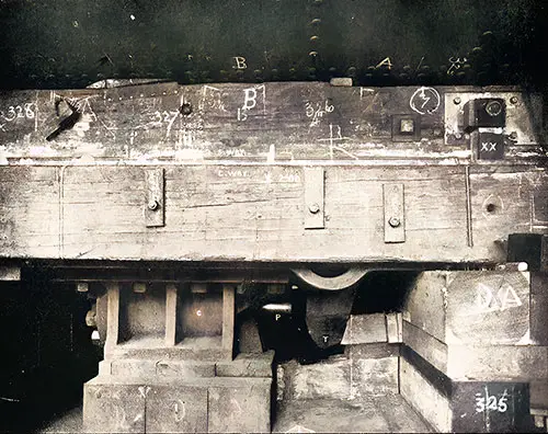
Fig. 38: One of the Hydraulic Launching Triggers. The Shipbuilder, Midsummer 1911. GGA Image ID # 10ba8f1823
Fig. 38 represents one of the two hydraulic triggers by which the vessel was held when all the shores and blocks were removed. Fig. 39 shows the pump and pressure gauge associated with the launching triggers. A striking photograph of the vessel immediately after leaving the ways is reproduced in Fig. 40.
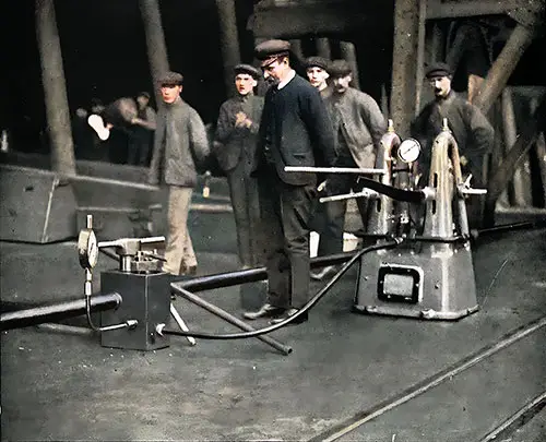
Fig. 39: Pump and Pressure Gauge Associated with Launching Trigger. Note the Six Staff Members by the Machinery. © Frank & Sons, So. Shields. The Shipbuilder, Midsummer 1911. GGA Image ID # 10baa927d0
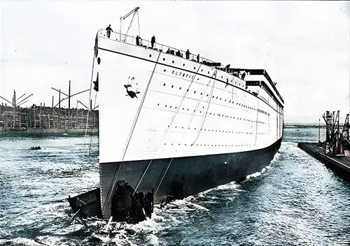
Fig. 40: The Launch of the Olympic - 20 October 1910. © Frank & Sons, So. Shields. The Shipbuilder, Midsummer 1911. GGA Image ID # 10bafda314
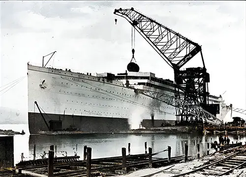
Fig. 41: Floating Crane Lifting a Boiler on Board the Olympic - 9 November 1910. The Shipbuilder, Midsummer 1911. GGA Image ID # 10bc208fd9
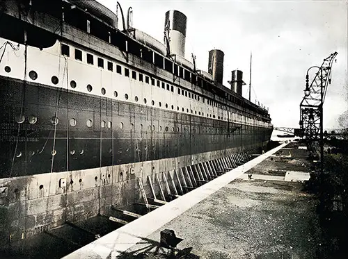
Figure 42: The Olympic in Graving Dock, 1 April 1911. The Terms “Dry Dock” and “Graving Dock” Refer to an Excavated Area Near a Wharf or River Where Vessels Are Placed for Examination, Cleaning, Caulking, Remanteling, Repairing, Painting, and Other Maintenance Activities. The Shipbuilder, Midsummer 1911. GGA Image ID # 10bc53fb27
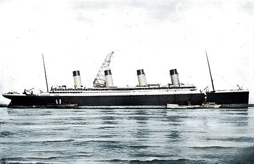
Fig. 43: Olympic Almost Completed. The Shipbuilder, Midsummer 1911. GGA Image ID # 10bca27be9
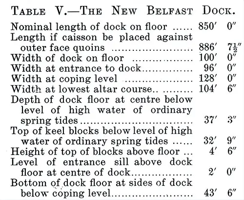
Table V: The New Belfast Graving Dock. The Olympic was docked on the 1st April, 1911, in the new graving dock belonging to the Belfast Harbor Commissioners, of which the principal dimensions are given in Table V., and which has the distinction of being the largest graving dock in the world at the present time. The Shipbuilder, Midsummer 1911. GGA Image ID # 10bcab60bf
The progress of work in connection with the SS Titanic is illustrated by the photographs we have used for that purpose in the case of the SS Olympic, the vessels having, as already stated, been built on adjoining berths.
However, it is interesting to note the dates upon which definite stages in constructing the second vessel were reached. The keel was laid on 31 March 1909, or about three months after the SS Olympic was commenced. By the 15 May following, the SS Titanic was framed to the height of the double bottom and was fully framed on the 6 April 1910, just a year after laying the keel.
The vessel was plated by 19 October 1910. It was successfully launched on 31 May 1911, with launching arrangements similar to those adopted for the SS Olympic. It is expected the Titanic will be completed and enter service early in 1912.
Key Highlights and Most Engaging Content
1️⃣ The Structural Design of Titanic and Olympic 🚢
🔹 The ships had eight steel decks at the midship section and an additional ninth deck at the bow and stern.
🔹 Figure 14 provides a cross-section of Titanic, showcasing her reinforced hull, bulkheads, and multiple decks.
🔹 The hull was built to withstand the immense pressures of transatlantic travel, while prioritizing passenger comfort and luxury.
🔹 Noteworthy Image: Fig. 14: Midship Section of Titanic and Olympic 📐
📌 Significance: This blueprint shows the ship’s internal layout, illustrating the sheer scale and engineering ingenuity behind Titanic’s construction.
2️⃣ Dimensions and Comparisons with Other Ships 📏
Table II provides a side-by-side comparison of Titanic with her contemporaries, such as:
🔹 Mauretania (90 feet shorter, 13,000 tons less).
🔹 Adriatic (141 feet shorter, 20,500 tons less).
🔹 Kaiser Wilhelm II (172 feet shorter, 25,600 tons less).
Titanic was larger than any ship ever built at the time, demonstrating the trend toward super-sized ocean liners.
🔹 Noteworthy Image: Table II: Dimensions of Titanic and Olympic 🏗️
📌 Significance: A must-see for students and maritime historians, showing how Titanic dominated shipbuilding innovation.
3️⃣ Riveting and Steel Framework 🔨
🔹 Titanic’s hull was assembled using over three million rivets, with hydraulic riveting used whenever possible for precision.
🔹 The largest rivets were 1¼ inches in diameter, weighing 1,200 tons total.
🔹 Hydraulic riveters, like the one shown in Figure 15, were essential in fastening the double bottom and hull plating securely.
🔹 Noteworthy Image: Fig. 15: Hydraulic Riveter at Work on the Vertical Keel Plate ⚙️
📌 Significance: Provides insight into the cutting-edge construction techniques used to assemble Titanic’s steel framework.
4️⃣ Titanic’s Stern and Propeller Design ⚙️
🔹 Titanic’s stern featured a triple-screw propeller arrangement, increasing efficiency and propulsion power.
🔹 The Siemens-Martin steel stern frame was manufactured away from the shipyard and later attached.
🔹 The central turbine propeller was housed in a special stern aperture, while the reciprocating propeller shafts were reinforced by boss arm castings.
🔹 Noteworthy Image: Fig. 17: Arrangement of Stern Castings 🔩
📌 Significance: Highlights the complexity of Titanic’s propulsion system, key to her performance at sea.
5️⃣ Watertight Doors and Safety Measures 🚧
🔹 Titanic’s watertight doors were designed to close instantly in an emergency, either from the bridge or automatically via water pressure-triggered floats.
🔹 The double-cylinder watertight doors, seen in Figure 21, used an electromagnetic friction clutch system, allowing for rapid closure across multiple decks.
🔹 These doors were intended to make Titanic “practically unsinkable”, reinforcing the belief that the ship could withstand severe damage.
🔹 Noteworthy Image: Fig. 21: Double Cylinder Watertight Door 🚪
📌 Significance: One of Titanic’s most infamous safety features, which ultimately failed to prevent her sinking.
6️⃣ The Construction Process: Photographic Timeline 🏗️
The series of construction photographs shows Titanic and Olympic’s progression from keel laying to final assembly.
Key milestones include:
🔹 Figure 22: Laying of Olympic’s keel on January 1, 1909.
🔹 Figure 28: Raising the last frame of Olympic, November 1909.
🔹 Figure 34: Titanic on the stocks next to Olympic, moments before Olympic’s launch.
🔹 Noteworthy Image: Fig. 34: Titanic and Olympic on the Stocks 🏗️
📌 Significance: A rare visual comparison of Titanic and Olympic during construction, perfect for students and researchers.
7️⃣ The Launch of Olympic and Titanic 🎇
🔹 Olympic was successfully launched on October 20, 1910, in a grand ceremony.
🔹 Titanic’s launch followed on May 31, 1911, nearly identical to Olympic’s.
🔹 The launching cradle and hydraulic triggers, shown in Figures 36-40, ensured a smooth descent into the water.
🔹 Noteworthy Image: Fig. 40: The Launch of Olympic - October 20, 1910 🚢
📌 Significance: Captures a historic moment—the first of the Olympic-class giants entering the ocean.
Relevance for Teachers, Students, Historians, and Genealogists
👨🏫 Teachers & Students:
🔹 Ideal for engineering, history, and maritime studies—providing primary-source material on shipbuilding methods.
🔹 Perfect for research papers on Titanic’s design and safety measures.
📜 Historians & Maritime Enthusiasts:
🔹 Offers unparalleled technical details on Titanic’s riveting, hull plating, and watertight compartments.
🔹 Photographs and blueprints make this an invaluable source for shipbuilding history.
🧬 Genealogists & Family Historians:
🔹 A rich resource for those with ancestors who worked at Harland & Wolff.
🔹 Lists construction dates, offering clues for tracing employment records and shipyard work logs.
Encouragement for Students: Essay & Research Topics
💡 Need Research Ideas?
How did Titanic’s hull design differ from previous ocean liners?
Were Titanic’s watertight doors truly effective?
What role did rivet quality play in Titanic’s sinking?
Compare Titanic’s construction to modern shipbuilding techniques.
🔥 Why Use GG Archives?
GG Archives provides authentic historical materials, helping students and researchers go beyond myths to uncover the real engineering story behind Titanic.
🚢 Step inside the shipyard and witness the making of Titanic—before she became history. 🌊

