Titanic’s Working Arrangements: Steering, Safety, and Crew Operations on a Floating City
📌 Explore the intricate working arrangements of the Titanic, from its advanced steering system and lifeboat davits to crew accommodations and submarine signaling. A must-read for historians, researchers, and maritime enthusiasts.
The Shipbuilder – Working Arrangements on the Titanic ⚓🚢🔧
Introduction: A Masterclass in Maritime Operations
The Titanic was not just an ocean liner—it was a floating city with a complex operational infrastructure. This section of The Shipbuilder (1911) provides a fascinating deep dive into the working arrangements aboard the Titanic and her sister ship, the Olympic. Covering navigation, steering, crew accommodations, cargo handling, lifeboat arrangements, and submarine signaling, this article showcases the intricate planning and technological innovations that went into managing one of the most advanced ships of its time.
For teachers, students, genealogists, and historians, this section is essential for understanding Titanic’s daily operations and how her crew managed everything from cargo loading to steering the ship through the North Atlantic. With detailed descriptions of the Titanic’s steering gear, lifeboat davits, crew quarters, cargo storage, and navigating bridge, this article brings the ship’s inner workings to life.
Table of Contents for This Section
1️⃣ The Crew: Who Ran the Titanic?
2️⃣ The Titanic’s Steering System: The Heart of Navigation
3️⃣ Anchors & Cargo Handling: Engineering Marvels
4️⃣ Lifeboat & Davit System: Preparing for Emergencies
5️⃣ Submarine Signaling: Cutting-Edge Safety Technology
6️⃣ Crew Accommodations: Life Aboard the Titanic
7️⃣ The Navigating Bridge: Commanding the Titanic
The working arrangements on board the Olympic and Titanic are necessarily on a scale in keeping with the great size of the vessels. The number of crew employed on board each ship for all purposes is about 860. Of these about 65 belong to the navigating department, 320 are employed in the engineers’ department, and 475 are engaged in the stewards’ and catering department.
The forward portion of the boat deck and the exposed decks at the ends of the vessel are entirely devoted to working and navigating appliances, while the management of the ship is also greatly facilitated by the working passage on the port side of E deck, which extends nearly the full length of this deck and is connected by stairways with all the principal departments.
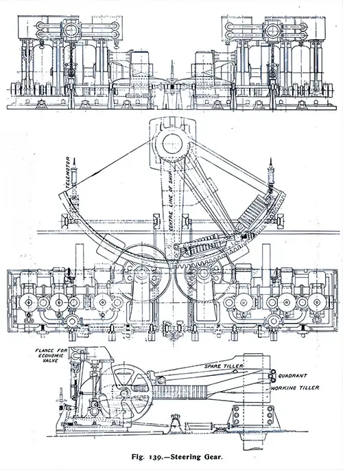
Fig 139: Steering Gear. The Shipbuilder, Midsummer 1911. GGA Image ID # 10e2d7fd20. Click to View a Larger Image.
The steering gear is a versatile system located in the poop deck at the end of the shelter deck. It is of the well-known Wilson-Pirrie type, manufactured by Harland & Wolff.
This system consists of a spring quadrant and a tiller on the rudder head. Either of two sets of three-crank vertical steam engines can operate the gear independently, with the other serving as a backup. The gear is operated through a wheel-and-pinion and bevel gearing mechanism.
Figure 139 illustrates the entire arrangement. The engines feature inverted direct-acting cylinders, each with a diameter of 17 inches and a stroke length of 18 inches. They operate using steam at a pressure of 100 pounds per square inch.
Piston steam valves have been implemented and are directly driven from the crankshaft using eccentrics. Each engine's cylinders are supported at the front by three wrought steel columns and at the back by three cast-iron columns.
Two cast iron columns also support the intermediate shaft, which connects the spur and bevel gears. Each engine is mounted on a sliding bed with adjusting screws, allowing it to be quickly engaged or disengaged from the quadrant when switching from one engine to the other.
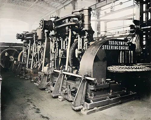
Fig. 140: Steam Steering Engines with Spur and Bevel Gearing. The Shipbuilder, Midsummer 1911. GGA Image ID # 10e30618ff
The crankshaft of each engine is provided with a spur-pinion which drives a spur wheel on the intermediate shaft, carried on the back columns of the engine. This intermediate shaft is connected by bevel gearing to a vertical shaft, a crucial connection that gears into the quadrant using a manganese bronze pinion above the bevel gearing. The role and significance of the bevel gearing in the engine system can be better understood by reference to Fig. 139 and the photograph of the engines given in Fig. 140.
The spur and bevel gear are of the Citroen type, a unique design made of cast steel throughout. They have machine-cut helical teeth of the herringbone shape. Experience has shown that this unique design is the most suitable form for minimum wear when the gears have to transmit power in either direction, as is the case with a steering engine. This is a testament to innovative engineering in the field.
The pitch is given approximately as the Citroen gears are not made to standard pitches. Their noiseless running is mainly obtained through a total absence of backlash, a crucial factor that ensures the smooth and efficient operation of the engine. This absence of backlash can only be achieved by calculating the exact pitch according to given diameters and a fixed number of teeth, which is why a special cutter is made for each set of gearing.
The sizes of the bevel wheels are:—pitch circle diameters, 5 feet 10½ inches and 2 feet 0½ inches; number of teeth, 19 and 55; pitch, about 4¼ inches; width of face, 11 inches. The teeth on both sides of the face are shrouded to the pitch line, and the total width over the shrouds is 14½ inches. Each bevel wheel weighs 1 ton 16 cwt, and each spur wheel weighs 1 ton 6 cwt. The spur pinion weighs about 5 cwt, and the bevel pinion weighs about 9 cwt. The quadrant and the pinion on the vertical shaft have machine-cut involute teeth.
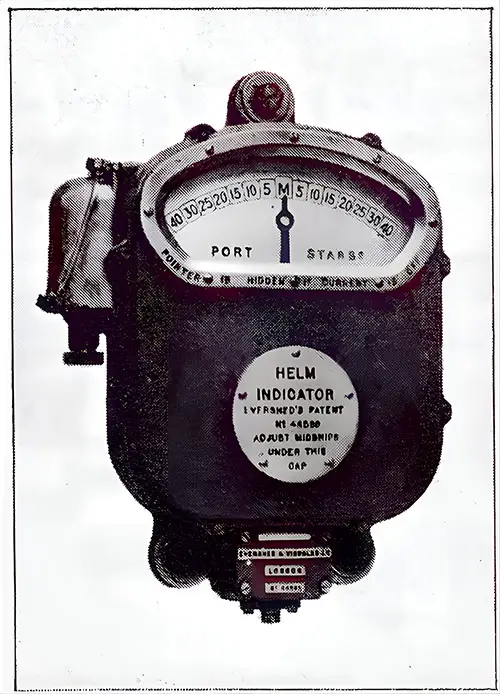
Fig. 141: Electric Helm Indicator. The Shipbuilder, Midsummer 1911. GGA Image ID # 10e331edea
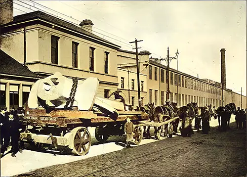
Fig. 142: 15 1/2 Ton Center Anchor Pulled by Horse-Drawn Flatbed Trailer. The Shipbuilder, Midsummer 1911. GGA Image ID # 10e34dffbd
The center anchor, which is illustrated in Fig. 142, weighs 15½ tons, and the side anchors each weigh 7¾ tons. The cables connected with the side anchors are 3⅜ inches in diameter and have a total length of 330 fathoms, weighing 96 tons.
The anchors are of Hall’s latest improved type and, with the cables, have been manufactured by Messrs. N. Hingley & Sons, Ltd., of Netherton, Dudley.
A powerfully built crane is fitted at the center line of the forecastle deck for handling the 15½-ton anchor, which is placed in a well on the deck immediately above the stem. The side anchors are housed in the hawse pipes in the usual manner.
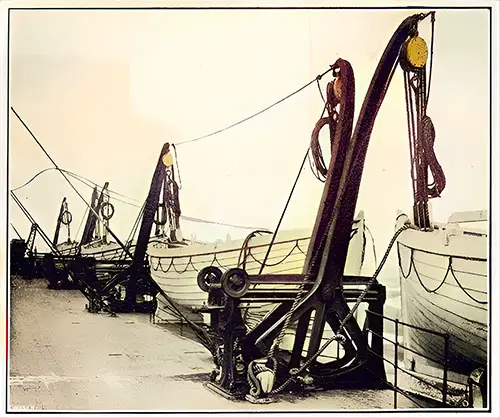
Fig. 143: Welin Double-Acting Boat Davits. The Shipbuilder, Midsummer 1911. GGA Image ID # 10e35823a4
The lifeboats, which are 30 feet long, are placed on the boat deck, as shown in Plate IV. The davits are of the Welin double-acting type manufactured by the Welin Davit and Engineering Co., Ltd., of London. Sixteen sets, specially designed for handling two or, if desired, three boats each, have been provided.
The double-acting system is not altogether new, as it was adopted by another company some time ago in the case of boats carried on the poop. Still, its employment on such a large scale is a distinct departure.
The well-known principle of the Welin davit is retained in all its simplicity, with the addition of a slight segmental increase at the inboard edge of the quadrant. This modification enables the arm to be swung right inboard to plumb the inboard boat, thereby saving the time-wasting operation of shoving and pulling the latter into position, which has to be done with davits of the ordinary type.
The arrangement for saving fore and aft deck space is also worthy of notice. Instead of having two standards between each boat, the standards are combined as a twin frame; see Fig. 143. The latter carries the two quadrants and all the necessary gear for operating the forward and after the boat at will.
The operating gear is also of an ingenious and interesting nature. For this purpose, a single handle is employed, driving a small pinion mounted upon a swing bar. The latter is thrown into or out of gear using a simple eccentric arrangement, which enables either screw of either davit to be worked independently of the other.
Four 15-cwt electric winches, supplied by the Sunderland Forge and Engineering Co., have been provided in the positions shown in Plate III for hoisting and lowering the boats. The chapter on electrical equipment describes these winches.
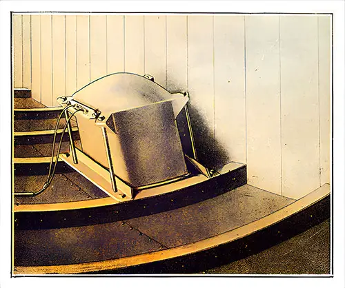
Fig. 144: Receiving Tank for Submarine Signals. The Shipbuilder, Midsummer 1911. GGA Image ID # 10e37573da
The signals are received by small tanks containing microphones placed inside the vessel's hull on the port and starboard sides below the water level; see Fig. 144.
These tanks, which may be termed the ship's "ears," are connected to a direction indicator on the navigating bridge (Fig. 145) by ordinary telephonic cable.
By moving the switch on the indicator box to the port, only the port "ear" is in operation. By changing the switch to the starboard "ear," the starboard "ear" commences its work. Assuming the bell is on the port side of the ship, sounds are received only by that "ear."
Should the bell be dead ahead, the sound will be heard equally by both "ears." The signals, therefore, warn of the ship's proximity to the point of danger and assist her progress in a fog, as the navigating officer can tell with more certainty where the boat is located.
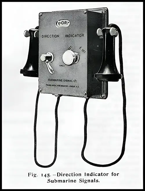
Fig. 145: Direction Indicator for Submarine Signals. The Shipbuilder, Midsummer 1911. GGA Image ID # 10e37637bc
Accommodation for Officers and Crew
Plates III, IV, and V show the officers' accommodation. They are in a house on the boat deck forward.
The engineers' quarters are on the middle deck, and their mess room, pantries, offices, etc., are on the deck above, adjoining the working passage.
The firemen have excellent accommodation on five decks forward. Two spiral staircases and a tunnel through the forward hold access to their quarters to the boiler rooms, keeping them entirely clear of the passenger accommodation.
The seamen's accommodation is placed on E deck forward. The living rooms for the stewards and catering staff are situated on the port side of the E deck and are entered from the working passage.
Cargo, Baggage, and Mails
To provide access for cargo or baggage to the lower holds, three cargo hatchways, placed at the centerline of the ship, have been fitted forward for Nos. 1, 2, and 3 holds; four hatchways have been provided aft, two placed at the centerline for Nos. 5 and 6 holds; and two smaller hatchways, away from the centerline, give access to No. 4 hold.
The hatchways to Nos. 1 and 2 holds are served by three steam winches. The third hatch near the passengers' quarters is served by two 2½-ton electric cranes and two 3-ton electric winches.
The two hatchways to No. 4 hold are each served by a 14-ton electric crane. The remaining hatchways, Nos. 5 and 6, are each served by two 2½-ton cranes and one 3-ton electric winch.
The masts, which are 205 feet above the average draught line, are utilized for working the cargo using cargo spans. At the same time, the foremast supports a derrick suitable for lifting motor cars, which will be stored in one of the foreholds.
The post office and baggage accommodation are arranged compactly on the lower and orlop decks forward to expedite the reception and despatch of mail and the transportation of passengers' baggage on the ship's departure and arrival.
The Navigating Bridge
The navigating bridge, from which the vessel is controlled, is situated at the forward end of the boat deck so that the navigating officer may have a clear view ahead.
This bridge is a veritable forest of instruments. In the center is the wheelhouse, containing the telemotor control wheel by which the ship is steered, with a standard compass immediately in front. In front of the wheelhouse are the engine room, docking, steering telegraphs, and loud-speaking telephones to various stations.
The watertight door controller, the submarine signal receiver, the helm indicator, the master clocks, and other apparatus are also located in the adjoining bridge shelter or chart room.
A docking bridge is provided right aft for use when the vessel is docking or turning in a confined space.
Key Highlights and Most Engaging Content
1️⃣ The Crew: Who Ran the Titanic? 👨✈️👨🔧🍽️
The Titanic had a crew of approximately 860, split into:
🔹 Navigating Department – 65 crew (captain, officers, lookouts, quartermasters).
🔹 Engineering Department – 320 crew (firemen, greasers, electricians, engineers).
🔹 Stewards & Catering Staff – 475 crew (chefs, stewards, attendants).
🔹 The ship was designed to keep crew operations efficient and separate from passenger areas to ensure smooth service.
🔹 A special working passage on E deck allowed crew members to move quickly between key departments without disrupting passengers.
🔹 Noteworthy Image: Fig. 139: Steering Gear
📌 Significance: This image illustrates the mechanics behind one of the most important parts of the Titanic’s operations—steering a ship of unprecedented size.
2️⃣ The Titanic’s Steering System: The Heart of Navigation 🧭⚙️
🔹 The Titanic used a Wilson-Pirrie steam-powered steering system, built by Harland & Wolff.
🔹 The steering engines had two independent systems, ensuring a backup in case of failure.
🔹 Bevel gears with machine-cut helical teeth (known as Citroen gears) minimized wear and tear, ensuring smooth and precise maneuvering.
🔹 An electric helm indicator on the bridge displayed the exact position of the rudder.
🔹 Noteworthy Image: Fig. 140: Steam Steering Engines with Spur and Bevel Gearing
📌 Significance: Highlights Titanic’s advanced steering mechanisms, which allowed for precision control of the vessel’s massive rudder.
🔹 Noteworthy Image: Fig. 141: Electric Helm Indicator
📌 Significance: This indicator enabled officers to see rudder movements in real time, helping with navigation, especially in emergencies.
3️⃣ Anchors & Cargo Handling: Engineering Marvels ⚓📦
🔹 The center anchor alone weighed 15 ½ tons, while the side anchors weighed 7 ¾ tons each.
🔹 Anchor chains weighed a total of 96 tons and were 330 fathoms (1,980 feet) long.
🔹 A powerful crane was installed on the forecastle deck to handle the center anchor.
Three main cargo hatchways forward and four aft allowed efficient loading of baggage, cargo, and mail.
Cargo handling equipment included:
🔹 Steam winches for heavy lifting.
🔹 Electric cranes for delicate cargo like motor cars.
🔹 A derrick for hoisting automobiles into the hold.
🔹 Noteworthy Image: Fig. 142: 15 ½ Ton Center Anchor Pulled by Horse-Drawn Flatbed Trailer
📌 Significance: Shows the massive scale of Titanic’s anchors and the technology needed to transport and install them.
4️⃣ Lifeboat & Davit System: Preparing for Emergencies 🛶⛑️
🔹 Titanic was equipped with 16 Welin double-acting boat davits, capable of holding up to three lifeboats per davit.
🔹 The double-acting davits were a new innovation, designed to swing lifeboats inward for easier boarding.
🔹 Four electric winches (15-cwt) were installed to assist in hoisting and lowering lifeboats.
🔹 Noteworthy Image: Fig. 143: Welin Double-Acting Boat Davits
📌 Significance: Highlights the advanced lifeboat launching system, which, had it been fully utilized, could have saved more lives on April 15, 1912.
5️⃣ Submarine Signaling: Cutting-Edge Safety Technology 🔊🚢
🔹 Titanic was equipped with submarine signaling equipment to detect nearby vessels in fog or low visibility.
🔹 Special microphones (called "ears") were placed below the waterline to detect sound signals from lighthouses, other ships, or underwater bells.
🔹 A direction indicator on the bridge helped officers determine the source of incoming sounds.
🔹 Noteworthy Image: Fig. 144: Receiving Tank for Submarine Signals
📌 Significance: Demonstrates early sonar-like technology that was ahead of its time for maritime safety.
🔹 Noteworthy Image: Fig. 145: Direction Indicator for Submarine Signals
📌 Significance: Allowed officers to pinpoint the location of nearby vessels, improving navigation in poor weather.
6️⃣ Crew Accommodations: Life Aboard the Titanic 🚢👨🍳
🔹 Officers were housed on the boat deck for easy access to the bridge.
🔹 Engineers had quarters on the middle deck, close to the working passage.
🔹 Firemen and stokers had their own dedicated staircases and tunnels to avoid interfering with passengers.
🔹 Stewards and catering staff were housed on E deck, near the passenger areas they served.
🔹 Noteworthy Image: Plates III, IV, and V (Crew Accommodation Layouts)
📌 Significance: These plans provide an invaluable look at where different crew members lived and worked on the Titanic.
7️⃣ The Navigating Bridge: Commanding the Titanic 🌊🚢
The bridge was equipped with state-of-the-art instruments, including:
🔹 A telemotor control wheel (for steering).
🔹 Engine room and docking telegraphs (for speed and maneuvering).
🔹 Watertight door controls and submarine signal receivers.
🔹 A separate docking bridge at the stern was used for maneuvering in tight spaces.
🔹 Noteworthy Image: Fig. 145: Navigating Bridge Equipment
📌 Significance: Showcases the sophisticated technology used to control one of the largest ships of its time.
Relevance for Teachers, Students, Historians, and Genealogists
👨🏫 Teachers & Students:
A perfect STEM lesson in mechanical engineering, maritime navigation, and crew management.
Encourages students to compare Titanic’s technology with today’s shipbuilding advancements.
📜 Historians & Maritime Enthusiasts:
One of the most detailed accounts of Titanic’s day-to-day operations.
Useful for understanding shipboard hierarchy and technological advancements of the era.
🧬 Genealogists & Family Historians:
Helps reconstruct the daily lives of crew members—particularly for those researching ancestors who worked as sailors, engineers, or stewards.
Encouragement for Students: Essay & Research Topics
💡 Need Research Ideas?
🔹 How did Titanic’s steering system work compared to modern ships?
🔹 What role did submarine signaling play in maritime safety?
🔹 How were crew members’ lives different based on their department?
🚢 The Titanic wasn’t just a ship—it was a technological masterpiece. ⚙️🔧

