
Titanic’s Electrical Marvel: The Power, Lights, and Innovation That Made a Ship a Floating City
📌 Explore the Titanic’s groundbreaking electrical system as detailed in The Shipbuilder (1911). Learn how 10,000 lamps, powerful dynamos, elevators, wireless telegraphy, and even electric baths transformed ocean travel. A must-read for historians, researchers, and maritime enthusiasts.
The Shipbuilder – Electrical Equipment on the Titanic ⚡🚢💡
Introduction: The Powerhouse of a Floating City
Electricity was the lifeblood of the Titanic, transforming it from just another ocean liner into a marvel of modern engineering. This section of The Shipbuilder (1911) gives an in-depth look at the ship’s vast electrical system, covering lighting, power generation, heating, cargo handling, communication, and even luxury features like electric elevators and baths.
For teachers, students, genealogists, historians, and maritime enthusiasts, this article offers a rare and comprehensive look into how electricity powered nearly every function aboard the Titanic. With detailed diagrams, images of dynamos, electric cranes, telephones, and Marconi wireless equipment, it is an indispensable resource for research and historical analysis.
Table of Contents for This Section
1️⃣ The Electrical Nerve Center: Titanic’s Power Plant
2️⃣ Lighting the Titanic: 10,000 Lamps at Sea
3️⃣ The Role of Electricity in Cargo, Communication, and Navigation
4️⃣ Luxury Meets Technology: Elevators, Electric Baths, and More
5️⃣ Wireless Telegraphy and the Future of Maritime Communication
6️⃣ The Titanic’s Electrical Legacy
ELECTRICITY, it need hardly be pointed out, is extensively employed in all the departments of the Olympic and Titanic. In addition to the large supply required for lighting purposes, electrical power is used for the deck cranes; cargo, boat, and engine room winches; passenger elevators; stores, mail, and pantry lifts; ventilating and stokehold fans; cabin fans; motors for the cylinder-lifting gear, turbine-turning and lifting gear, and condenser sluice valves; the workshop machine tools; conveyor for marconigrams; gymnastic apparatus; kitchen and pantry machinery, such as the ice-rocker, dough-mixers, potato-peelers, roasters, knife-cleaners, mincers, hot plates, and electric irons; electric heaters; electric baths; main steam whistles; sounding machines; stoking indicators; boiler room telegraphs; clocks; watertight doors; helm indicator; illuminated pictures; chimes; bells; loud-speaking and service telephones; submarine signaling; and wireless telegraphy.
The electrical installation, therefore, may virtually be termed the nerve system of the ship. Indeed the application of electricity is so general that much of the electrical equipment is necessarily described in the other sections of this book.

Fig. 122: Arrangement of Electric Engine Room (Schematic). The Shipbuilder, Midsummer 1911. GGA Image ID # 10dcf7f38c. Click to View a Larger Image.
The central station is situated in a separate watertight compartment, about 63 feet long and 24 feet high, adjoining the after end of the turbine room at the tank top level. The general arrangement of the electrical machinery in this compartment is shown in Fig. 122.
The main generating plant consists of four 400-kilowatt engines and dynamos manufactured by Messrs. W. H. Allen, Son & Co., of Bedford. It has a collective output of 16,000 amperes at 100 volts, which exceeds the current capacity of many large city central stations. The switchboard gallery is at the forward end of the compartment at the orlop deck level and commands a view of the machines.
The engines are of the vertical three-crank compound forced-lubrication type and indicate 580 horse-power each, running at 325 revs per minute. Each engine has one high-pressure cylinder 17-inch diameter and two Auxiliary Generating- Sets. Main Generating: Sets.
Low-pressure cylinders are 20 inches in diameter and have a stroke of 13 inches in diameter. Steam is supplied at 185 pounds pressure and is exhausted into the surface heater, the condition at sea, or into the auxiliary condenser, which is the condition in port.
Each engine is coupled directly to a compound-wound continuous-current dynamo of the ten-pole type fitted with inter-poles. The equalizer cables are led to the switches below the deck near the center of the compartment to minimize and equalize the resistance when running in parallel.
Illustrations of one of the generating sets are given in Figs. 123 and 124. Hans Renold's silent chains drive the Renold's meters.

Fig. 123: Sectional Elevation of one of the Main Generating Sets. The Shipbuilder, Midsummer 1911. GGA Image ID # 10dd05dd62. Click to View a Larger Image.
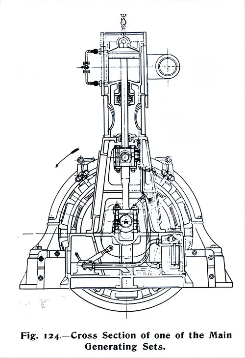
Fig. 124: Cross Section of one of the Main Generating Sets. The Shipbuilder, Midsummer 1911. GGA Image ID # 10dd4a84f1

Fig. 125: Switch Gear of Dynamos 3 and 4. The Shipbuilder, Midsummer 1911. GGA Image ID # 10dd59f991
Current is conveyed from the Main dynamos utilizing the Switch Gear. Heavy rubber-insulated cables, each of 1.5 square inch sectional area and 2 1/4 inch diameter, to the dynamo control switches on the switchboard gallery's front. Of these, there are four, one for each dynamo, each provided with five hand levers resembling those commonly seen in a railway signal box; see Fig. 125.
The electrician in charge faces the machinery when operating the switches. He can also communicate his instructions to the engineer below utilizing electrically illuminated signals, indicating if any particular set will be started, stopped, or varied in speed. The various switches are interlocked to ensure correct operation.
Four ammeters, reading up to 5,000 amperes each, are provided, and there are also four integrating wattmeters, which record the number of units generated by the several dynamos. Four revolving voltmeters are mounted on a stand between the dynamo pillars and indicate the electrical pressure at the lighting and power bus bars and any individual dynamo for guidance in coupling or uncoupling the sets.

Fig. 126: Main Feeder Switchboard. The Shipbuilder, Midsummer 1911. GGA Image ID # 10dd72f3e9
From the main dynamo switches, the current passes by insulated cables below the gallery to the feeder switchboard. The latter consists of 25 black polished slate panels mounted on the fuses, automatic cut-outs, and ammeters for controlling each circuit.
Fig. 126 shows a general view of the feeder switchboard and its attendant apparatus, which Messrs. Dorman & Smith of Salford, Manchester, constructed to the shipbuilders' specifications.

Fig. 127: Electrical Distribution Box. The Shipbuilder, Midsummer 1911. GGA Image ID # 10de24d17c
From the feeder switchboard, radiate no fewer than 48 cables, ranging in area up to 61/12 S.W.G. The distribution of current is affected by the single-wire system. Still, the returns are carried back and bonded in such a way as to avoid stray currents.
The power and heating supply can be run entirely independent of the lighting supply, with power and light bus bars on the switchboard that can be paralleled or otherwise, as may be required.
The cables pass vertically up two steel trunk ways, one on the starboard and one on the port side, and terminate in master fuse boxes at each deck, from whence branch the individual circuit cables. The latter ramify throughout the vessel along the main passages of the different decks and feed, in turn, the distribution boxes, one of which is illustrated in Fig. 127.
From the distribution boxes, the current is taken by wiring to the individual lights, motors, heaters, etc. Local switches are, of course, provided for turning off individual lights or machines.

Fig. 128: Electric Heater. The Shipbuilder, Midsummer 1911. GGA Image ID # 10de3c34fc
There are 520 electric heaters installed throughout each vessel of the Prometheus type, illustrated in Fig. 128. These heaters take a collective current of over 5,000 amperes.

Fig. 129: 2 1/2 Ton Electric Crane. The Shipbuilder, Midsummer 1911. GGA Image ID # 10deac106e
Electrical driving has been adopted to secure minimum noise and vibration for cargo cranes and winches near passenger accommodations. Eight electric cargo cranes have been supplied to each ship by Messrs. Stothert and Pitt, Ltd., of Bath, six having a capacity of 2½ tons each and two of 1½ tons each.
Two of the 2½-ton cranes are placed at the third hatch forward (see Plate III.) and have a radius of 27 feet, a height from the deck to the center of the pulley of 29 feet, and a total lift of 100 feet. The remaining four 2½-ton cranes are placed at the after hatches, Nos. 5 and 6. The radius is somewhat greater than in the case of the forward cranes, two having a radius of 28 feet And the other two 29 feet.
However, the height to the center of the pulley is slightly less, being 27 feet and 26 feet, respectively, instead of 29 feet. For all the 2½-ton cranes, the hoisting motor is 40 B.H.P., and the slewing motor is 5 B.H.P. The lifting speed at full load is 160 feet per minute, 113, and the slewing speed is 500ft. per minute. The lifting speed increases automatically for lighter loads. One of the 2½-ton cranes is shown in Fig. 129.
The two 1½-ton cranes are placed at the after end of the promenade deck and serve the two small hatches to No. 4 hold. Their radius is 21 feet, the height between the deck and pulley is 20 feet, and the total lift is 80 feet. Each crane is fitted with a hoisting motor of 30 B.H.P. and a slewing motor of 3 B.H.P. The lifting speed at full load is 200 feet per minute, and the slewing speed is 500 feet per minute.

Fig. 130: 3-Ton Electric Cargo Winch. The Shipbuilder, Midsummer 1911. GGA Image ID # 10deadcf14
Four 3-ton electric cargo winches and four 15-cwt Boat-hoisting winches have been supplied to each ship by the Sunderland Forge and Engineering Co., Ltd. and have been so designed by the makers that vibration and noise are practically eliminated. In the case of both sizes, the lifting speed is 100 feet per minute at full load.
As the winches are situated on the open decks, the working parts and motors are enclosed and watertight. The warping ends are driven through worm gearing of very substantial construction, the whole being enclosed and running in an oil bath. Ball thrust blocks are provided on the worm shafts.
The motors are series-wound and equipped with all the necessary control gear. A magnetic brake and a foot brake are provided on each side of the winch, the latter being interlocked with the controller to prevent unskilled operators from abusing the motor.
The controllers and resistances are built to withstand the roughest treatment. The makers have paid particular attention to the insulation of the current-carrying parts due to the damp and salty atmosphere to which the machines will be exposed. One of the winches is illustrated in Fig. 130.
Electric winches are also in the engine room to support the lifting gear, which Messrs. Chambers, Scott, and Co. of Motherwell supplied.
The winding gear for each of the first—and second-class passenger elevators, which have already been described when dealing with passenger accommodation, is driven by a motor of the four-pole totally enclosed shunt-wound type, rated at 6 B.H.P. when running at a speed of 500 revs per minute. The rating is based on a six-hour run with full load and a temperature rise not exceeding 70° F.

Fig. 131: 10 cwt. Stores Lift. The Shipbuilder, Midsummer 1911. GGA Image ID # 10dec394b1
Besides the passenger elevators, there is, on each ship, a 3-cwt electric service lift in the officer's pantry and another in the restaurant pantry. The latter travels from the saloon to the bridge deck, a height of 19 feet 6 inches, and has a cage 1 foot 7 inches by 2 feet 2 inches by 2 feet 6 inches.
There is also a 10-cwt store lift (depicted in Fig. 131) for carrying- provisions, etc., from the storerooms to the saloon deck, a height of 33 feet 6 inches, and an 8-cwt lift forward for raising mail bags.
All the service lifts are electrically controlled by push buttons at each deck. Position indicators and speaking tubes are also provided. All the lifts have been constructed and fitted by Messrs. R. Waygood & Co., Ltd., of London.

Fig. 132: One of the Electric Baths, Open. The Shipbuilder, Midsummer 1911. GGA Image ID # 10ded6eefe
Two electric bathrooms of the most modern type have been arranged adjacent to the Turkish baths at the middle deck level. Figs. 132 and 133 illustrate the kind of bath fitted. Fig. 132 shows the bath open, and Fig. 133 shows the bath closed up and in use.

Fig. 133: One of the Electric Baths, In Use. The Shipbuilder, Midsummer 1911. GGA Image ID # 10dee5d50d

Fig. 134: One of the Master Clocks. The Shipbuilder, Midsummer 1911. GGA Image ID # 10df0ecd83
The clocks, of which there are 48 throughout each vessel, have been supplied by the Magneta Time Co., Ltd., and all are actuated electrically on the Magneta system, which obviates the use of galvanic batteries. They are controlled by two master clocks placed in the chat room so they may work in complete unison, and each register simultaneously. One of the master clocks is illustrated in Fig. 134.
As is well known to ocean travelers, the ship's ships can gain over half an hour each day when going westwards and lose a corresponding amount when returning to Europe. To allow for this difference in time, the master clocks are set each day at noon by the officer in charge, who puts them backward or forwards according to the longitude.

Fig. 135: Loud-Speaking Telephone. The Shipbuilder, Midsummer 1911. GGA Image ID # 10df4cc8bd
The telephone installation of the SS Olympic and SS Titanic is divided into two sections, viz., the navigating group and the internal system.
All the apparatus is of the latest type and installed on the most approved lines. The navigating group provides for communication between the following:
- The wheelhouse on the bridge and the fore castle.
- The wheelhouse on the bridge and the crow's nest.
- The wheelhouse in the engine room.
- The wheelhouse on the bridge and the poop.
- The chief engineer's cabin and the engine room.
- The engine room and Nos. 1, 2, 3, 4, 5 and 6 stokeholds.
The instruments employed are Messrs. Alfred Graham and Co.'s patent loud-speaking navy phones of the type illustrated in Fig. 135.
Except for the chief engineer, the telephones are of the "Universal" pattern by which calls are given using an interrupter and voice. The apparatus is mounted in special forms to suit the various positions.
On the forecastle and poop, the instruments are contained within a polished brass casing mounted on a pillar. The whole fitting is arranged in portable form so that the apparatus can be used at two alternative positions in the case of the forecastle set and at a second position on the poop. The crow's nest telephone is mounted within a metal hood, and this set is also portable.
Four instruments are fitted in the wheelhouse of the navigating bridge. Each telephone is provided with an indicating device, and, in addition to a flag showing as is usual, a signal lamp is caused to glow upon a call being received.
Three telephones are employed in the engine room. The instrument for communicating with the boiler rooms operates with a combined switch and indicator, giving both lamp and flag signals, as in the case of the bridge instruments.
In each boiler room, the telephone is mounted within a metal hood. A special calling receiver and a visual indicator are provided at each station. The telephone in the chief engineer's room is of the cabin type.
The current for operating the system is obtained from the ship's circuit, which is reduced to a pressure suitable for telephonic work utilizing resistances. Introducing inductance coils eliminates the commutation noise inherent in the machine-generated supply. A standby battery is also provided and introduced in the circuit should the main supply fail using an automatic switch.

Fig. 136: Telephone Exchange Switchboard. The Shipbuilder, Midsummer 1911. GGA Image ID # 10df529f1e
The internal system provides for intercommunication between several cabins through a central exchange. The exchange switchboard has a capacity of 50 lines. The stations connected are several first-class staterooms, the rooms of the chief officials, and various service rooms.
The switchboard, which is illustrated in Fig. 136, is arranged to give a lamp signal upon a call being made. In addition to the usual audible signal, a voice call can be given to the exchange from any station in connection to ensure rapid operation.
The user at one of the cabins has to pick up the telephone and say the station he wishes to speak to right away, and a loud receiver at the exchange gives the instructions.
The operator, seeing a lamp glowing corresponding with the calling station, then connects the station with the station required, thus obviating the usual delay in communicating with the station and ascertaining the position required.
The current supply is obtained from the lighting circuit, as in the case of the navigating telephone system, and the automatic switch and standby battery are contained within the exchange switchboard casing.

Fig. 137: Cabin Telephone. The Shipbuilder, Midsummer 1911. GGA Image ID # 10df8c15e7
The telephone sets in each cabin are of Graham's intermediate loud-speaking type (Fig. 137) and comprise a handset with a circular metal push and terminal box. The fittings are silver-plated in most positions and polished and lacquered brass in others.
The system's wiring has been planned on the most approved principles, and junction boxes have been introduced to facilitate testing and extension of the installation. In addition to the exchange system, a separate group of circuits is provided for direct communication between the following:—
- First-class pantry (port) and galley.
- First-class pantry (port) and baker's shop
- First-class pantry (port) and butcher's shop
- Second-class pantry and baker's shop
- Second-class pantry and galley.
- First-class pantry (starboard) and galley.
These telephones are identical to those on the exchange system. A three-way switch and indicator box are fitted in the first-class pantry, and two-way switches and indicators are provided in the baker's shop and second-class pantry.
Messrs. Alfred Graham & Co. manufactured the telephones and fittings at their Crofton Park Works, London, and their staff carried out the installation on board.

Fig. 138: Connections of 1 1/2 KW Marconi Converter Set. The Shipbuilder, Midsummer 1911. GGA Image ID # 10df93a930. Click to View a Larger Image.
The wireless telegraphy installation consists of a Marconi 1½-kilowatt standard ship's set. The house for the Marconi instruments situated on the boat deck adjoining the officer's; see Plate III. The two parallel aerial wires required for the system extend between the masts, as indicated in Plate III.
They are kept as high as possible and fastened to light booms, the latter attached to the masts. Connecting wires are led to the instruments in the house from the aerial wires. There are two complete sets of apparatus, one for transmitting and one for receiving messages, the latter in a sound-proof chamber built in one corner of the house.
It does not lie within the province of this work to describe in detail the Marconi apparatus, but to give some indication of its nature, Fig 138, showing the connections of a 1½-kilowatt converter set, has been reproduced from an interesting article on the subject by Mr. W. W. Bradfield in a recent number of The Electrician, to which we would refer readers desiring further information.
Auxiliary Generating Sets
In addition to the four main generating sets, there are two 30-kilowatt engines and dynamos situated on a flat in the engine casing at the saloon deck level, well above the water line. The general features of their design are similar to the main sets, except that the engines are of the two-crank compound type.
Each engine has cylinders 9 inch and 12 inch diameter by 5 inch stroke, and runs at 380 revs, per minute. The auxiliary sets are connected utilizing a separate steam pipe to boilers in either of several boiler rooms and will be available for emergency use should the main sets be temporarily put out of action.
Cables
The main cables and branch wires are of tinned copper covered with rubber and heavily braided, except in the machinery spaces, where they are lead-sheathed, armored, and externally braided. In the boiler rooms, the cables run on steel pipes to protect against damp and mechanical injury.
All wires leading through a watertight bulkhead are collected in a steel tube filled with bitumen to ensure watertightness and look neat. Some idea of the extent of the electrical system will be gathered when it is stated that considerably more than 200 miles of cable have been fitted on each ship.
Electric Lighting
The total number of incandescent lamps installed on board the SS Olympic is about 10,000, ranging from 16 c.p. to 100 c.p., with the Titanic having a similar number. Tantalum lamps have been adopted throughout, except in a few cases in the engine room.
Metal filament lamps have been found quite suitable for use on shipboard except where there is any pronounced vibration. Their use permitted the voltage to be reduced to 100. The economy secured by the reduced voltage more than compensates for the higher first cost of the metal filament lamps compared with the ordinary incandescent pattern.
In the first-class staterooms, in addition to the usual fixed lights, there are fitted sockets for portable electric lamps or fans. Special dimming lamps with two filaments are also provided so that the light of small candle-power can be kept burning throughout the night, which will appeal to nervous passengers.
Emergency lamps on distinct circuits, deriving current from the emergency dynamos, are placed at intervals in all the passages, public rooms, and compartments throughout the vessel so that, in the unlikely event of an entire extinction of the ordinary lighting, there would still be illumination available at all the points where the passengers and crew would congregate. Anyone could find their way from one end of the vessel to the other at night utilizing the lights on these circuits.
Electric Motors
An idea of the large number of motors required will have been gathered from the numerous types of electrically driven machinery already cited. Altogether, there are 150 motors on board, varying from ½ to 40 H.P. Of these, 76 are employed in moving the ventilation fans and take a collective current of 5,250 amperes.
The hand and automatic control method adopted for the fan motors has already been dealt with when describing the stokehold fans and the ventilation and heating arrangements.
Next to the fan motors, as regards the amount of power absorbed, come the various motor-driven machines and mechanisms in the engine rooms, the cargo cranes and winches, the elevators and hoists, and the domestic machinery.
Illuminated Signs and Pictures
A number of electrically illuminated signs are distributed throughout the first—and second-class accommodation to direct passengers to the respective main entrances and public rooms.
In the gymnasium, attractive illuminated multi-colored pictures of sections of the Olympic and Titanic and a map of the world with a network of the many White Star steamship routes that encircle the globe are on view.
Key Highlights and Most Engaging Content
1️⃣ The Electrical Nerve Center: Titanic’s Power Plant ⚙️🔋
🔹 Titanic’s electrical plant was so advanced that it rivaled the power output of many small cities.
🔹 The main generating station was located in a watertight compartment near the turbine room and housed four 400-kilowatt engines and dynamos, collectively generating 16,000 amperes at 100 volts.
🔹 Additional auxiliary generators were installed above the waterline for emergency power in case the main plant failed.
🔹 Noteworthy Image: Fig. 122: Arrangement of Electric Engine Room (Schematic)
📌 Significance: This detailed schematic of Titanic’s power generation system reveals the complexity and scale of its electrical infrastructure.
🔹 Noteworthy Image: Fig. 123: Sectional Elevation of One of the Main Generating Sets
📌 Significance: Illustrates the massive engines and dynamos that provided electricity to every part of the Titanic, from lighting to cargo cranes.
2️⃣ Lighting the Titanic: 10,000 Lamps at Sea 💡🚢
🔹 Titanic had approximately 10,000 incandescent lamps, ranging from 16 to 100 candle-power, illuminating cabins, hallways, public rooms, and workspaces.
🔹 Dimmable lamps were installed in first-class staterooms, allowing passengers to control brightness at night.
🔹 Emergency lighting circuits ensured that, even in the event of generator failure, critical areas remained illuminated.
🔹 Noteworthy Image: Fig. 128: Electric Heater
📌 Significance: Highlights how electricity was used for comfort, ensuring warmth in cabins, public spaces, and crew quarters.
🔹 Noteworthy Image: Fig. 134: One of the Master Clocks
📌 Significance: Titanic’s clocks were synchronized electrically, ensuring that time adjustments for longitude changes were seamless.
3️⃣ The Role of Electricity in Cargo, Communication, and Navigation ⚓📦📞
🔹 Electric cargo cranes and winches allowed for efficient loading and unloading of heavy goods.
🔹 Electric telephones connected key areas of the ship, including the bridge, engine room, crow’s nest, and stokeholds.
🔹 The ship’s helm indicator, boiler room telegraphs, and loud-speaking phones were all electrically powered.
🔹 Noteworthy Image: Fig. 129: 2 ½ Ton Electric Crane
📌 Significance: Illustrates the modern cargo-handling equipment that made Titanic’s loading and unloading process efficient and less labor-intensive.
🔹 Noteworthy Image: Fig. 135: Loud-Speaking Telephone
📌 Significance: Titanic’s ship-wide communication system was an advanced feature for 1912, ensuring that critical orders could be transmitted instantly.
4️⃣ Luxury Meets Technology: Elevators, Electric Baths, and More 🏨🔼🛁
🔹 Titanic had three first-class electric elevators, an innovation that made travel between decks effortless.
🔹 Two second-class elevators provided additional convenience for passengers.
🔹 Electric Turkish baths and a swimming pool were included among the ship’s many high-tech amenities.
🔹 Noteworthy Image: Fig. 132: One of the Electric Baths, Open
📌 Significance: Highlights the use of electric heat for relaxation and wellness, a rare luxury even in five-star hotels at the time.
🔹 Noteworthy Image: Fig. 137: Cabin Telephone
📌 Significance: Shows how first-class passengers could enjoy private, in-room telephone service—an unheard-of convenience at sea in 1912.
5️⃣ Wireless Telegraphy and the Future of Maritime Communication 📡🌊
🔹 Titanic was equipped with a Marconi wireless telegraph system, allowing passengers and crew to send and receive messages from shore.
🔹 The system operated on a 1½-kilowatt standard ship's set, with two parallel aerial wires stretched between the masts.
🔹 Wireless communication was a groundbreaking feature, crucial in Titanic’s final hours as distress signals were sent across the Atlantic.
🔹 Noteworthy Image: Fig. 138: Connections of 1 ½ KW Marconi Converter Set
📌 Significance: Demonstrates how Titanic’s wireless system was set up, reinforcing its role in early 20th-century maritime safety and communication.
Relevance for Teachers, Students, Historians, and Genealogists
👩🏫 Teachers & Students:
A perfect case study for STEM (Science, Technology, Engineering, and Mathematics) education.
Helps illustrate the role of electricity in modernizing ocean travel.
📜 Historians & Maritime Enthusiasts:
One of the most detailed sources on Titanic’s electrical infrastructure, useful for research on early 20th-century ship design.
🧬 Genealogists & Family Historians:
If ancestors worked in Titanic’s engine room, electrical plant, or communications department, this article helps recreate their daily experiences.
Encouragement for Students: Essay & Research Topics
💡 Need Research Ideas?
How did Titanic’s electrical system compare to other ships of the era?
What role did wireless telegraphy play in Titanic’s final hours?
How did electricity improve safety and luxury aboard the Titanic?
🚢 Titanic was more than a ship—it was a technological revolution at sea. ⚡💡